Oil gas defrosting system and method for condensation method oil-gas recovery device

A recovery device and condensation method technology, applied in separation methods, chemical instruments and methods, steam condensation, etc., can solve problems such as increased oil-gas side resistance, blockage of oil-gas channels, affecting normal operation of oil-gas recovery devices, etc., to speed up defrosting speed Effect

Active Publication Date: 2020-08-14
山东冰轮海卓氢能技术研究院有限公司 +1
View PDF12 Cites 3 Cited by
  • Summary
  • Abstract
  • Description
  • Claims
  • Application Information

AI Technical Summary

Problems solved by technology

[0004] When the oil and gas are condensed through the heat exchanger, the water vapor in the oil and gas will condense into frost, and the frost layer will gradually thicken with time, and the oil an

Method used


Image

  • Oil gas defrosting system and method for condensation method oil-gas recovery device
  • Oil gas defrosting system and method for condensation method oil-gas recovery device
  • Oil gas defrosting system and method for condensation method oil-gas recovery device

Examples


Embodiment Construction

[0027] Describe the technical scheme of the present invention in detail below in conjunction with accompanying drawing:

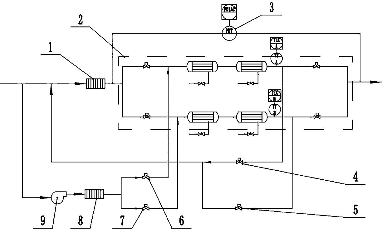
[0028] like figure 1 and 2 , An oil and gas defrosting system for a condensation method oil and gas recovery device, the oil and gas recovery device comprises an oil and gas inlet and an oil and gas outlet, and also includes a primary heat exchange installed between the oil and gas inlet and the oil and gas outlet in turn and used for condensing oil and gas 1 and post-stage heat exchange module 2.

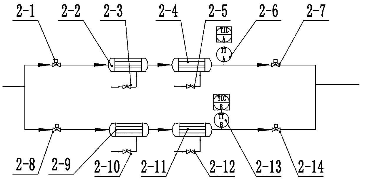
[0029] like figure 2 , the heat exchange module is provided with two parallel heat exchange branches A and B.

[0030] The heat exchange branch A is provided with oil and gas inlet valve A2-1, secondary heat exchanger A2-2, tertiary heat exchanger A2-4 and oil and gas outlet valve A2-7 in sequence along the oil and gas flow direction, and the secondary heat exchanger A2-2 is connected with the secondary liquid supply valve A2-3, and the tertiary heat exchan...


PUM


Abstract

The invention discloses an oil gas defrosting system and method for a condensation method oil gas recovery device. The oil gas recovery device comprises an oil gas inlet and an oil gas outlet and further comprises a heat exchange module installed between the oil gas inlet and the oil gas outlet and used for condensing oil gas, and the defrosting system comprises a heat exchange branch A and a heatexchange branch B which are arranged in the heat exchange module and connected in parallel. The oil gas defrosting system further comprises an induced draft fan, a heat exchanger, a defrosting inletvalve A, a defrosting inlet valve B, a defrosting outlet valve A and a defrosting outlet valve B. By means of branch switching, frosting of the heat exchanger is avoided, and normal operation of the recovery device is guaranteed.

Description

technical field [0001] The invention relates to an oil and gas defrosting system for an oil and gas recovery device, and also relates to a defrosting method based on the system. Background technique [0002] In the process of production, transportation and sales of petroleum and its products, some light liquid components will be vaporized, and if they are discharged into the atmosphere, they will cause loss of oil products, environmental hazards and potential safety hazards. In view of the importance of oil and gas recovery to production safety, energy conservation and emission reduction, and environmental protection, the Ministry of Environmental Protection has successively issued a series of oil and gas pollutant emission standards, and put forward specific requirements for oil and gas emission concentration and oil and gas treatment efficiency. [0003] Existing commonly used oil and gas treatment methods include adsorption method, absorption method, membrane separation m...

Claims


Application Information

Patent Timeline
IPC IPC(8): B01D5/00B01D53/00
CPCB01D53/002Y02P70/10
Inventor 张超徐树伍刘昌丰罗琼香张浩杰侯丽艳王飞虎白惠元
Owner 山东冰轮海卓氢能技术研究院有限公司
Why Eureka
Try Eureka