
Clamp structure for machining of automobile rear axle

A technology for automobile rear axles and fixtures, which is applied in the direction of manufacturing tools, metal processing, metal processing equipment, etc., can solve the problems of high investment cost, inability to adjust the angle, and affect the processing efficiency of automobile rear axles, so as to facilitate processing operations and improve The effect of stability

Pending Publication Date: 2020-08-14
DEZHOU VOCATIONAL & TECHN COLLEGE
View PDF10 Cites 9 Cited by
  • Summary
  • Abstract
  • Description
  • Claims
  • Application Information

AI Technical Summary

Problems solved by technology

If it is a vehicle driven by the front axle, then the rear axle is just a follower bridge, which only plays a load-bearing role. Its structure is mainly composed of a skeleton and plates covering the surface of the skeleton. These plates need to be welded. It is fixed on the frame, and the rear axle of the car is usually fixed and clamped by special clamps during processing, but the traditional clamps are relatively simple, and when it is clamped, its angle cannot be adjusted , resulting in the need to adjust the position of a single car rear axle multiple times during the process of processing, and in the process of position adjustment, it needs to be loosened and clamped multiple times, which seriously affects the processing efficiency of the car rear axle in the process of processing , while the clamping structure of some large manipulators is more flexible in use, but its initial investment cost is too high

Method used


Image

  • Clamp structure for machining of automobile rear axle
  • Clamp structure for machining of automobile rear axle
  • Clamp structure for machining of automobile rear axle

Examples


Embodiment Construction

[0025] The following will clearly and completely describe the technical solutions in the embodiments of the present invention with reference to the accompanying drawings in the embodiments of the present invention. Obviously, the described embodiments are only some, not all, embodiments of the present invention. Based on the embodiments of the present invention, all other embodiments obtained by persons of ordinary skill in the art without making creative efforts belong to the protection scope of the present invention.

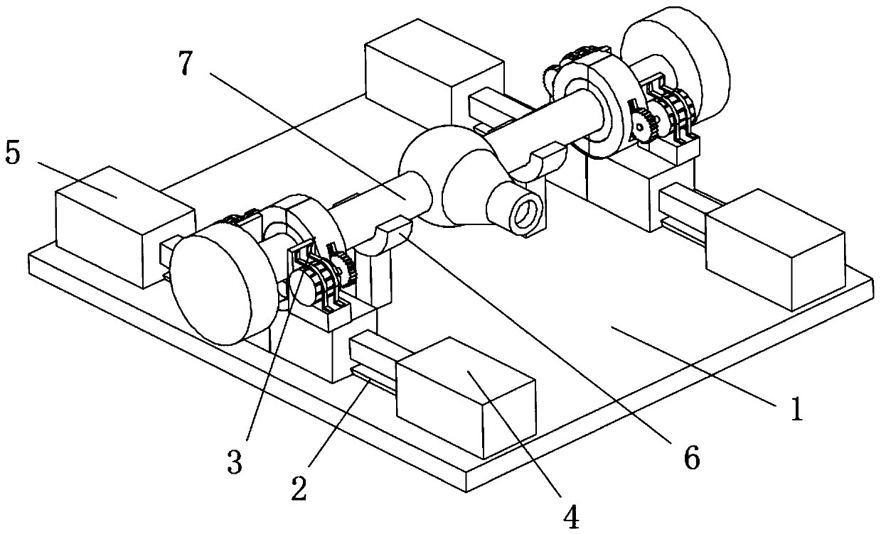
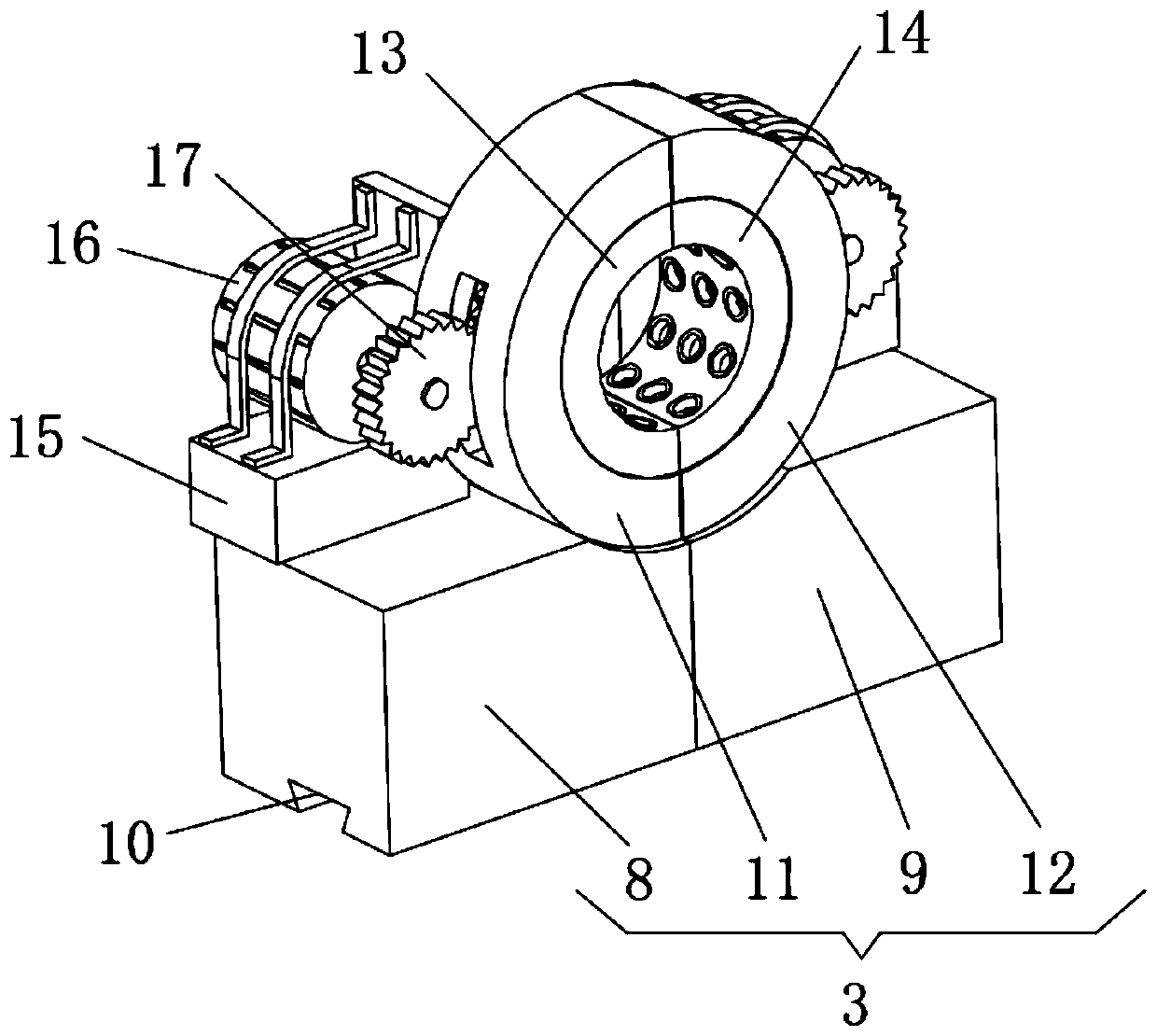
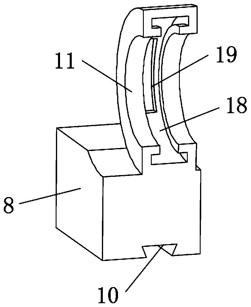
[0026] see Figure 1-6 , the present invention provides a technical solution: a fixture structure for automobile rear axle processing, including an operating table 1 and a guide rail 2 arranged on the operating table 1, the front side of the guide rail 2 is provided with a first-stage telescopic electric cylinder 4, and its rear end A secondary telescopic electric cylinder 5 is provided, and a clamp mechanism 3 is slidably provided on the guide rail 2, and a p...


PUM


Abstract

The invention discloses a clamp structure for machining of an automobile rear axle. The clamp structure comprises an operating table and guide rails arranged on the operation table, first-stage telescopic electric cylinders are arranged on the front sides of the guide rails, second-stage telescopic electric cylinders are arranged behind the first-stage telescopic electric cylinders, clamp mechanism bodies are arranged on the guide rails, a placement seat is arranged in the direction close to the inner side of the clamp mechanism body, the placement seat is fixedly welded to the table top of the operating table through a supporting rod, the automobile rear axle is arranged on the placement seat in an erected mode, and the guide rails, the clamp mechanism bodies, the first-stage telescopic electric cylinders and the second-stage telescopic electric cylinders are all arranged in groups. The set of clamp mechanism bodies is symmetrically arranged above the operating table, the clamp mechanism bodies are arranged to be composed of first-stage sliding seats, second-stage sliding seats, first-stage mounting seats and second-stage mounting seats, first-stage clamping seats and second-stageclamping seats are mounted in the second-stage mounting seats and the second-stage mounting seats, and thus the clamping seats can rotationally adjust the angle of the automobile rear axle through the driving effect of a stepping motor when clamping the automobile rear axle, so that the automobile rear axle is subjected to machining operation conveniently.

Description

technical field [0001] The invention relates to the related technical field of automobile rear axle processing, in particular to a fixture structure for automobile rear axle processing. Background technique [0002] The rear axle of a car refers to the bridge behind the car. If it is a vehicle driven by the front axle, then the rear axle is just a follower bridge, which only plays a load-bearing role. Its structure is mainly composed of a skeleton and plates covering the surface of the skeleton. These plates need to be welded It is fixed on the frame, and the rear axle of the car is usually fixed and clamped by a special clamp during processing, but the traditional clamp is relatively simple, and its angle cannot be adjusted when it is clamped , resulting in the need to adjust the position of a single car rear axle multiple times during the process of processing, and in the process of position adjustment, it needs to be loosened and clamped multiple times, which seriously a...

Claims


Application Information

Patent Timeline
Patent Type & Authority Applications(China)
IPC IPC(8): B23K37/04B23K37/047
CPCB23K37/0443B23K37/047B23K2101/006
Inventor 王海平霍雷刚薛丽芳
Owner DEZHOU VOCATIONAL & TECHN COLLEGE
Features
  • Generate Ideas
  • Intellectual Property
  • Life Sciences
  • Materials
  • Tech Scout
  • Unparalleled Data Quality
  • Higher Quality Content
  • 60% Fewer Hallucinations
Learn More