Pavement drainage well lid for sponge city

A drainage manhole cover and sponge city technology, applied to drainage structures, waterway systems, water supply devices, etc., can solve the problems of low drainage efficiency, easy to fall into debris, etc., and achieve the effect of reducing difficulty

Active Publication Date: 2020-08-14
山西久丰智造科技股份有限公司
View PDF8 Cites 4 Cited by
  • Summary
  • Abstract
  • Description
  • Claims
  • Application Information

AI Technical Summary

Problems solved by technology

[0005] The object of the present invention is to solve the above-mentioned problems of low drainage efficiency and easy falling of sundries, to provide a sponge city pavement drainage manhole cover with drainage efficiency and avoiding the falling of sundries

Method used


Image

  • Pavement drainage well lid for sponge city
  • Pavement drainage well lid for sponge city
  • Pavement drainage well lid for sponge city

Examples


Embodiment 1

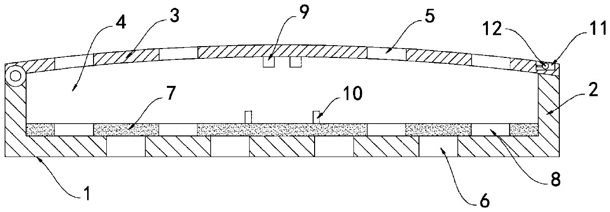
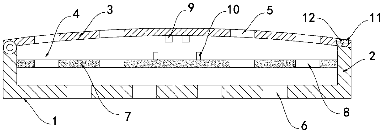
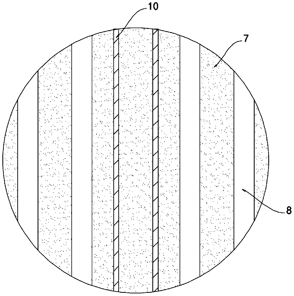
[0021] Such as Figure 1-4 As shown, a pavement drainage manhole cover for a sponge city comprises a cover body 1. The cover body 1 includes a water storage tank 2 and a cover plate 3 hinged above the water storage tank 2. The upper surface of the cover plate 3 is provided with a receiving groove 11, and the receiving tank The bottom surface of 11 is hinged with a handle 12. The handle 12 can be convenient for the staff to lift and open the cover plate 3. When the handle 12 is not in use, it can be stored in the accommodation tank 11 to avoid affecting road traffic. The water storage tank 2 is provided with a water storage chamber 4. The cover The surface of the plate 3 is provided with a plurality of equidistant strip-shaped water inlet holes 5, and the bottom surface of the water storage tank 2 is provided with a plurality of drain holes 6, and the inner wall of the water storage tank 2 is sealed and slidably connected with a floating plate 7, and the floating plate 7 There ...

Embodiment 2

[0026] Such as Figure 5 As shown, the difference between this embodiment and Embodiment 1 is that the bottom surface of the cover body 1 is rotatably connected with a threaded cylinder 13, the side wall of the threaded cylinder 13 is provided with a plurality of fan blades 14 in an annular array, and the lower surface of the cover plate 3 The surface is fixedly connected with a vertical threaded rod 15. The lower end of the threaded rod 15 runs through the floating plate 7 and the water storage tank 2 in turn and extends into the threaded cylinder 13. The threaded rod 15 is threadedly matched with the threaded cylinder 13.

[0027] In this embodiment, when it rains in the city, there is a large amount of rainwater converging above the cover body 1, and road vehicles pass by the cover body 1, which is easy to splash water on both sides of the road, affecting the normal passage of pedestrians on both sides of the road. At the same time, the wheels press against the cover plate ...


PUM


Abstract

The invention belongs to the field of sponge city construction, and particularly relates to a pavement drainage well lid for a sponge city. The pavement drainage well lid for the sponge city comprisesa lid body. The lid body comprises a water storage tank and a lid plate hinged to the upper portion of the water storage tank, a water storage cavity is formed in the water storage tank, and a plurality of strip-shaped water inlet holes are formed in the surface of the lid plate at equal intervals. A plurality of drainage holes are formed in the bottom face of the water storage tank, a floating plate is slidably and hermetically connected to the inner side wall of the water storage tank, a plurality of water seepage holes are formed in the floating plate, the water seepage holes and the drainage holes are staggered and interspersed, the lid plate is arranged in an upwards-arched arc shape, and permanent magnet blocks are fixed to the lower end of the lid plate. Two strip-shaped elastic pieces are slidably arranged on the surface of the floating plate. The well lid can be kept in a sealed state in rainless weather, garbage and other sundries are prevented from falling into a drainage well to cause blockage, odor in the drainage well is prevented from wafting out and polluting the environment, and the well lid can be automatically opened to drain rainwater in rainy weather.

Description

technical field [0001] The invention belongs to the field of sponge city construction, and in particular relates to a pavement drainage manhole cover for a sponge city. Background technique [0002] Under the new situation, the sponge city is an innovative expression of promoting the construction of green buildings, the development of low-carbon cities and the formation of smart cities. In the construction of sponge cities, pavement drainage wells play a key role in the drainage, purification and collection of urban rainwater. [0003] Most of the existing drainage well covers are provided with drainage holes with larger diameters on the well covers, and the rainwater is discharged through the drainage holes. However, the size of the drainage holes of this type of well cover is limited. Slow, low efficiency, easy to cause the problem of road surface water affecting vehicle traffic, and external garbage and other debris are easy to fall into the well from the drain hole, cau...

Claims


Application Information

Patent Timeline
Patent Type & Authority Applications(China)
IPC IPC(8): E03F5/06E03F5/10E03F7/02
CPCE03F5/06E03F5/10E03F7/02E03F2005/061
Inventor 官春玲张琼
Owner 山西久丰智造科技股份有限公司
Why Eureka
Try Eureka