A compressed oxygen self-rescuer for easy escape in coal mine

An oxygen self-rescuer and self-rescuer technology, applied in the field of compressed oxygen self-rescuers, can solve the problems of restricting escape, unable to judge the escape path, unable to see clearly, etc., to achieve the effect of improving comfort and precious survival time

Active Publication Date: 2022-05-24
嘉兴量创科技有限公司
View PDF0 Cites 0 Cited by
  • Summary
  • Abstract
  • Description
  • Claims
  • Application Information

AI Technical Summary

Problems solved by technology

[0003] When a fire breaks out in an underground coal mine, it will not only produce a large amount of toxic gases such as carbon monoxide, which will make the underground workers unable to breathe, but will also produce a large amount of smoke
These thick smoke will block the sight of the underground staff, causing the staff to be unable to see the nearby road conditions and judge the correct escape route, which greatly limits the possibility of escape

Method used


Image

  • A compressed oxygen self-rescuer for easy escape in coal mine
  • A compressed oxygen self-rescuer for easy escape in coal mine
  • A compressed oxygen self-rescuer for easy escape in coal mine

Examples


Embodiment 1

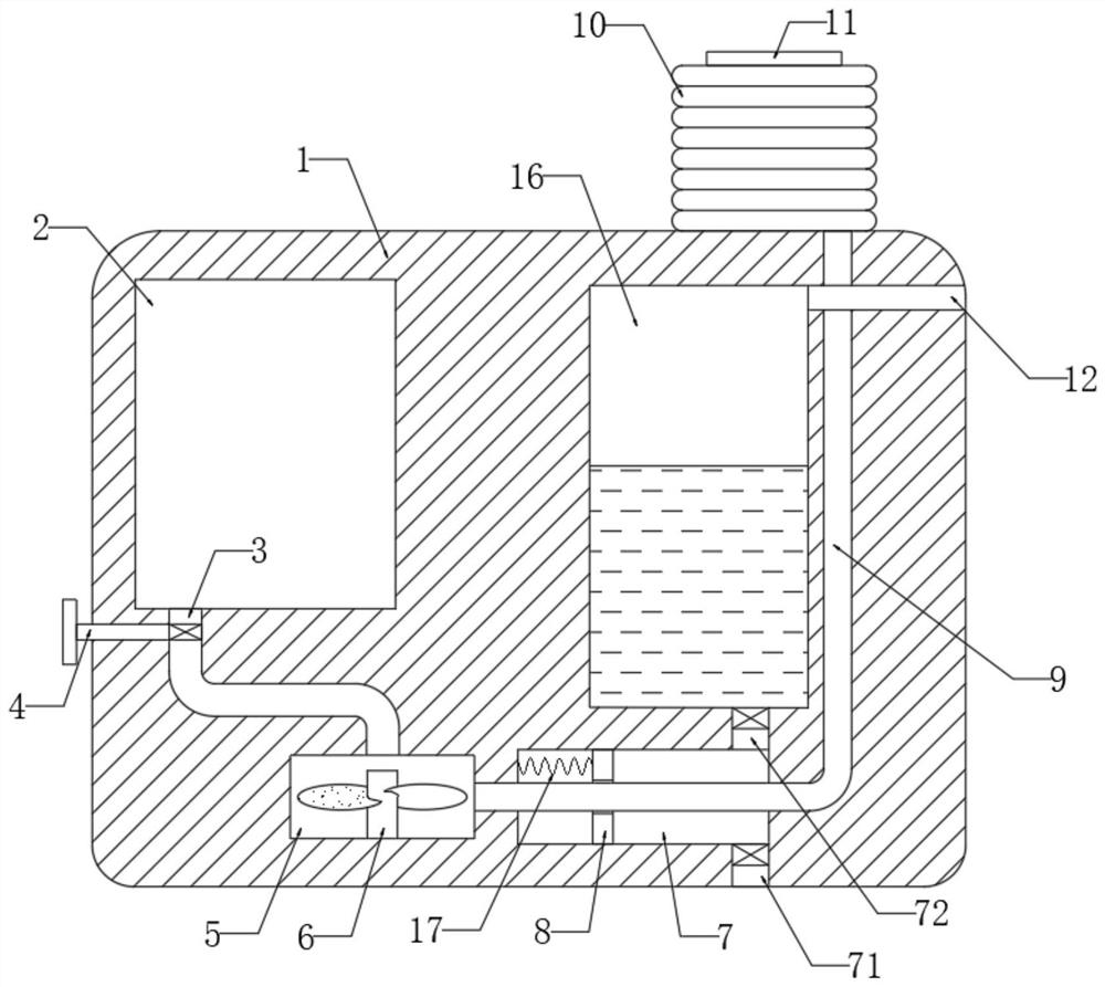
[0020] refer to figure 1 , a compressed oxygen self-rescuer that is easy to escape underground in a coal mine, comprising a self-rescuer body 1, an oxygen storage chamber 2 is opened on the side wall of the self-rescuer body 1, an airbag 10 is fixedly connected to the upper end of the self-rescuer body 1, and the upper end of the airbag 10 is installed There is a breathing mask 11 communicating with it.

[0021] The side wall of the self-rescuer body 1 is provided with a circular groove 5, the inner bottom of the circular groove 5 is rotatably connected with a centrifugal fan 6, and an air intake pipe 3 is communicated between the circular groove 5 and the oxygen storage chamber 2, and the air intake pipe 3 A control valve 4 is installed, an air outlet pipe 9 is communicated between the circular groove 5 and the air bag 10, and a bar-shaped groove 7 is opened on the side wall of the self-rescuer body 1, and an iron sliding plug 8 is sealed and slidably connected in the bar-sha...

Embodiment 2

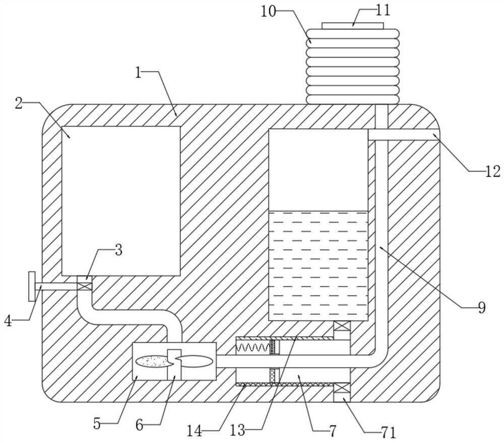
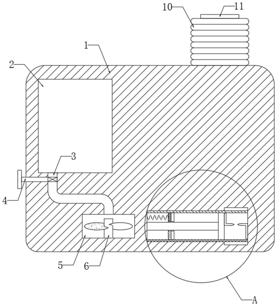
[0031] refer to Figure 2-4 , the difference from the first embodiment is that the inner top of the strip groove 7 is fixedly connected with a rubber plate 13, the inner bottom of the strip groove 7 is fixedly connected with a glass plate 14, and the side walls of the slide plug 8 are fixedly connected from top to bottom. There is a fur layer 82 and a silk layer 81 , and a hollow cavity 15 is opened on the side wall of the self-rescuer body 1 .

[0032] It should be noted that the fur layer 82 and the silk layer 81 are only provided on a part of the left side of the sliding plug 8 , for details, please refer to the manufacture Figure 4 , so that the fur layer 82 and the silk layer 81 can be rubbed against the rubber plate 13 and the glass plate 14 , and the side wall of the slide plug 8 and the inner wall of the strip groove 7 have good air tightness.

[0033] And the rubber plate 13 and the glass plate 14 both extend into the hollow cavity 15 , the two opposite inner walls ...


PUM


Abstract

The invention discloses a compressed oxygen self-rescuer which is easy to escape underground in a coal mine. The upper end of the upper end of the self-rescuer is equipped with a breathing mask communicating with the inside. The side wall of the self-rescuer body is provided with a circular groove. The inner bottom of the circular groove is rotatably connected to a centrifugal fan. The gap between the circular groove and the oxygen storage chamber An air inlet pipe is connected, and a control valve is installed in the air inlet pipe, an air outlet pipe is connected between the circular groove and the airbag, and a strip groove is opened on the side wall of the self-rescuer body. The present invention draws the smog-containing air near the self-rescuer body into the strip groove and then discharges it into the water storage tank, so that the smoke in the air can be removed, the smoke concentration near the self-rescuer body is greatly reduced, and the escape personnel can see clearly Road conditions and fire conditions, so as to make a correct judgment and escape successfully.

Description

technical field [0001] The invention relates to the technical field of coal mine underground equipment, in particular to a compressed oxygen self-rescuer that is easy to escape underground in a coal mine. Background technique [0002] Compressed oxygen self-rescuer, also known as isolated compressed oxygen self-rescuer, is a reusable self-rescuing escape device that uses high-pressure compressed oxygen as an oxygen source, and plays a key role in escaping underground in coal mines. [0003] When a fire breaks out in a coal mine, not only a large amount of toxic gases such as carbon monoxide will be produced, making the underground workers unable to breathe, but also a large amount of smoke will be produced. These thick smoke will block the sight of the underground staff, so that the staff cannot see the nearby road conditions and cannot judge the correct escape route, which greatly limits the possibility of escape. In view of this, the application document itself proposes a...

Claims


Application Information

Patent Timeline
Patent Type & Authority Patents(China)
IPC IPC(8): E21F11/00E21F17/18E21F17/00A62B7/02
CPCE21F11/00E21F17/00E21F17/18A62B7/02
Inventor 孙凤秋
Owner 嘉兴量创科技有限公司
Why Eureka
Try Eureka