A cathode plate with protrusions and depressions, a bipolar plate, and a fuel cell
A cathode plate and metal plate technology, applied in the direction of fuel cells, fuel cell components, circuits, etc., can solve problems that no researchers have studied
- Summary
- Abstract
- Description
- Claims
- Application Information
AI Technical Summary
Problems solved by technology
Method used
Image
Examples
Embodiment 1
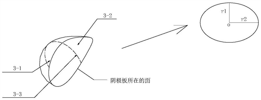
[0059] Embodiment 1, a semi-droplet-shaped projection of a fuel cell flow field structure, the three-dimensional shape of the semi-droplet-shaped projection includes: a tail and a head, the tail 3-1 and the head 3-2 The intersection surface 3-3 is a semicircular surface;
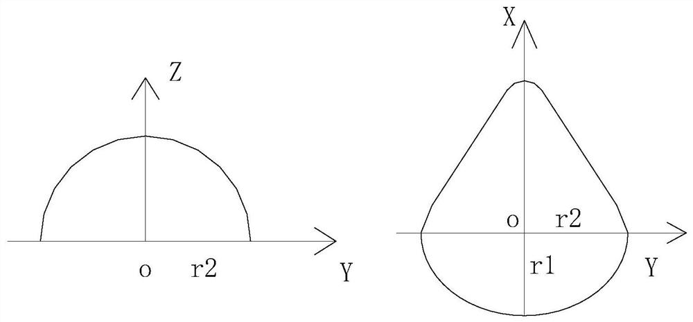
[0060] The tail is a semi-ellipsoid (semi-ellipsoid), and along the direction of the tail to the head, its cross-sectional area gradually increases until the intersection surface 3-3 (the surface perpendicular to the cathode plate) reaches the maximum; along the tail In the direction of the head, the cross-sectional area of the head 3-2 gradually decreases.
[0061]The direction that the tail points to the head is the X direction, the direction perpendicular to the X direction and on the cathode plate surface is the Y direction, and the direction perpendicular to the cathode plate surface is the Z direction, and the X direction, Y direction, and Z direction form a three-dimensional right angle coordinate ...
Embodiment 2
[0081] Embodiment 2: The subject of Embodiment 2 is to study: how to arrange protrusions and depressions.
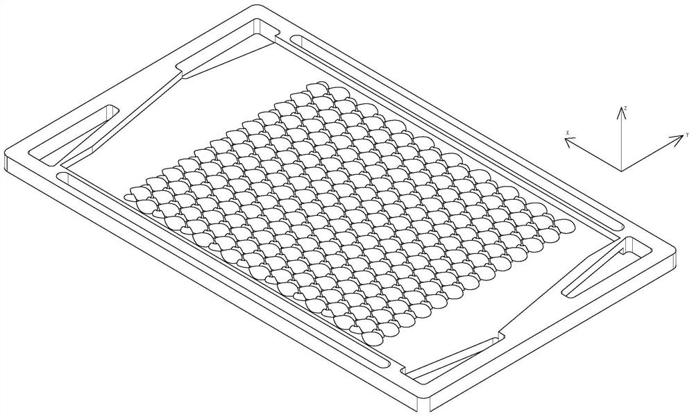
[0082] From attached figure 1 It can be seen that the design of the half-water droplet convex array on the cathode plate (half-water droplet concave array on the cathode plate) is also related to its arrangement design in addition to the shape of a single protrusion (depression).
[0083] In order to meet the maximization of protrusion and depression, such as Figure 9 As shown, the shape of the protrusion and the depression is the same, no matter what its shape is, the distance Sx=L of the protrusion (depression) along the X direction;
[0084] The length from the first vertex to the second vertex is L.
[0085] As for Sy, Sy≤2×r2, but its exact solution is difficult to be expressed by formula.
[0086] Based on the analysis of the first embodiment, it can be seen that when r1=r2, the tail is a hemisphere, and the corresponding effect is the best. In particular, the...
Embodiment 3
[0088] Cathode plate semi-water drop projection (cathode plate half water drop concave array) is applied to the cathode plate in the fuel cell bipolar plate;
[0089] Such as figure 1 As shown, the cathode plate 1 (using a rectangular metal plate) is provided with an air inlet 8 and an air outlet 9, and the air inlet 8 and the air outlet 9 are arranged at the corners of the cathode plate 1, and the air inlet 8 and the air outlet 9 are Diagonal arrangement; a flow field structure is arranged in the middle of the cathode plate 1;
[0090] The flow field structure includes: a half-droplet-shaped projection array on the cathode plate, and a half-droplet-shaped concave array on the cathode plate;
[0091] The cathode plate half-drop-shaped projection array includes: several cathode plate half-drop-shaped projections, and the cathode plate half-drop-shaped projections are arranged in a quincunx shape;
[0092] The array of semi-drop-shaped recesses on the cathode plate includes: s...
PUM
 Abstract
Description
Claims
Application Information
 - R&D
- Intellectual Property
- Life Sciences
- Materials
- Tech Scout
- Unparalleled Data Quality
- Higher Quality Content
- 60% Fewer Hallucinations
Browse by: Latest US Patents, China's latest patents, Technical Efficacy Thesaurus, Application Domain, Technology Topic, Popular Technical Reports.
© 2025 PatSnap. All rights reserved.Legal|Privacy policy|Modern Slavery Act Transparency Statement|Sitemap|About US| Contact US: help@patsnap.com


