
Boring cutter and design method

A boring tool and tool holder technology, which is applied in the field of high-diameter boring tools and their design, can solve problems such as prone to severe vibration and damage to the boring machine system, and achieve the effect of improving processing quality and reducing vibration

Inactive Publication Date: 2020-07-10
CHANGZHOU INST OF TECH
View PDF0 Cites 0 Cited by
  • Summary
  • Abstract
  • Description
  • Claims
  • Application Information

AI Technical Summary

Problems solved by technology

[0004] The boring tool and design method provided by the present invention solve the problem that the boring tool is prone to severe vibration during the boring process and easily cause serious damage to the boring machine system, significantly reduces the vibration of the boring tool during the boring process, and improves Processing quality

Method used

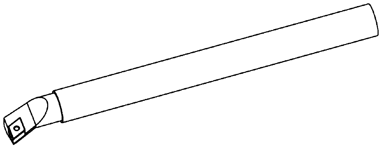

Image

  • Boring cutter and design method
  • Boring cutter and design method
  • Boring cutter and design method

Examples


Embodiment Construction

[0034] Embodiments of the present invention are described in detail below, examples of which are shown in the drawings, wherein the same or similar reference numerals designate the same or similar elements or elements having the same or similar functions throughout. The embodiments described below by referring to the figures are exemplary only for explaining the present invention and should not be construed as limiting the present invention.

[0035] Embodiments of the present invention will be described in detail below in conjunction with the accompanying drawings.

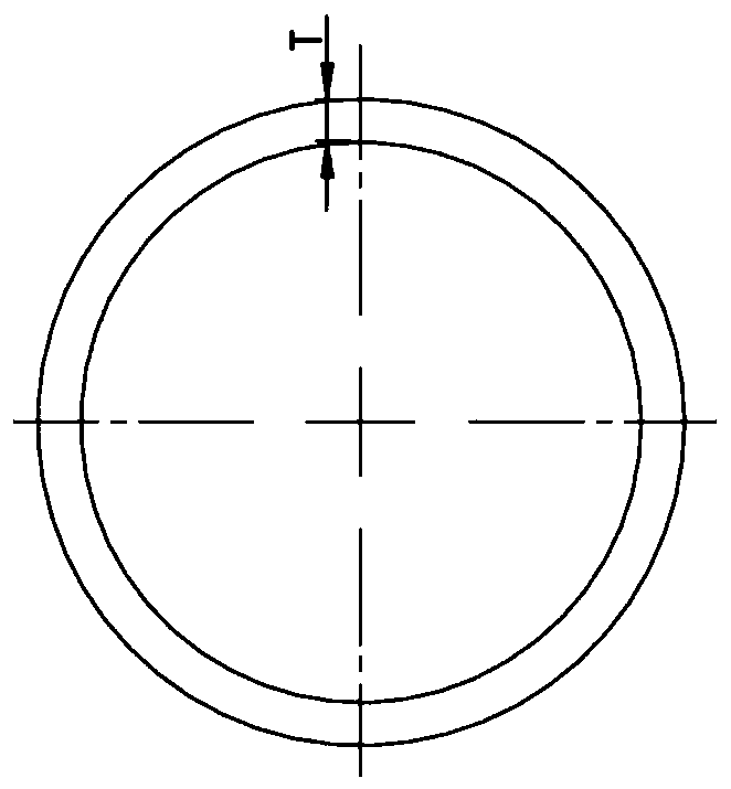
[0036] One aspect of the present invention discloses a boring tool, see figure 1 and figure 2 , including a damping alloy sleeve 1, a cutter bar 2 and a cutter head assembly 3. Preferably, the damping alloy sleeve 1 is a high manganese-based damping alloy material that has a damping coefficient similar to that of rubber and whose strength is similar to that of low-carbon steel. The outer diameter of the boring...


PUM


Abstract

The invention provides a boring cutter and a design method. The boring cutter comprises a damping alloy sleeve, a cutter bar and a sleeve head assembly, wherein force transmission is realized betweenthe damping alloy sleeve and the cutter bar by adopting an interference fit mounting mode, the damping alloy sleeve is mounted on the outermost layer of the cutter bar, and the deformation of the damping alloy sleeve and the cutter bar gradually decreases from the outer side to the central position until zero. The design method of the boring cutter comprises the following steps: acquiring an original three-dimensional design model of the boring cutter, designing the damping alloy sleeve 1, establishing key design parameters including wall thickness T and length L, and determining variable intervals of each parameter; through finite element analysis, with the wall thickness T and the length L as variables, obtaining a bending stiffness matrix [kb] of the boring cutter under the combined variables and a structural damping ratio matrix [zeta] under each stiffness value; and introducing a vibration resistance value parameter theta and determining the optimal design scheme of the boring cutter. The problem that an existing boring cutter is prone to violent vibration in the boring process and consequently a boring machine system is prone to being seriously damaged is solved.

Description

technical field [0001] The invention relates to the technical field of machine tool processing, in particular to a boring tool with a high multiple diameter and a design method thereof. Background technique [0002] Boring cutters are widely used in machine tool processing. They are mainly used to cut the inner circle of the workpiece. The structure mainly includes arbor and cutter head. During the boring process, due to the existence of cutting force, the cutting force acts on the workpiece while , also reacts on the boring tool, which causes the boring tool and the workpiece to vibrate during the boring process, and the more serious situation is that the tool chatters, which will directly cause the boring machine system to produce severe vibration and strong noise, which will affect both the workpiece and the boring tool have a more serious impact. [0003] In order to solve such problems, there are two types of solutions. The first type of solution is to add a dynamic sh...

Claims


Application Information

Patent Timeline
Patent Type & Authority Applications(China)
IPC IPC(8): B23B27/16B23B29/00G06F30/23G06F30/17
CPCB23B27/16B23B29/00
Inventor 盛冬平李晓贞徐红丽门艳钟何亚峰
Owner CHANGZHOU INST OF TECH
Learn More