Destroying device for used syringes

A technology for destroying devices and syringes, which is applied to hypodermic injection devices, devices introduced into the body, waste collection and transfer, etc. It can solve the problems of low work efficiency, troublesome operation, inconvenient collection, etc., and achieve high work efficiency and convenient operation. Effect

Active Publication Date: 2020-08-18
NANJING HANXIYUE AUTOMATION TECH CO LTD
View PDF9 Cites 5 Cited by
  • Summary
  • Abstract
  • Description
  • Claims
  • Application Information

AI Technical Summary

Problems solved by technology

[0005] In order to overcome the disadvantages of not being able to collect the syringes and needles conveniently, the operation is cumbersome, and the syringes cannot be destroyed, resulting in the need for additional operations to destroy the syringes, and the shortcomings of low work efficiency, the purpose of the present invention is to provide a When the syringe is crushed, the syringe and the needle are collected, which is easy to operate and has a high working efficiency. The syringe is destroyed after use.

Method used


Image

  • Destroying device for used syringes
  • Destroying device for used syringes
  • Destroying device for used syringes

Examples


Embodiment 1

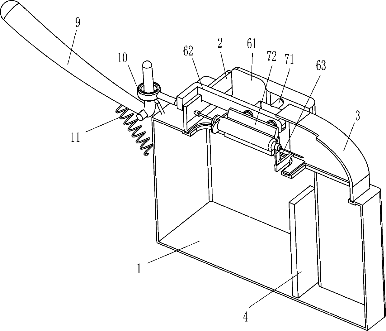
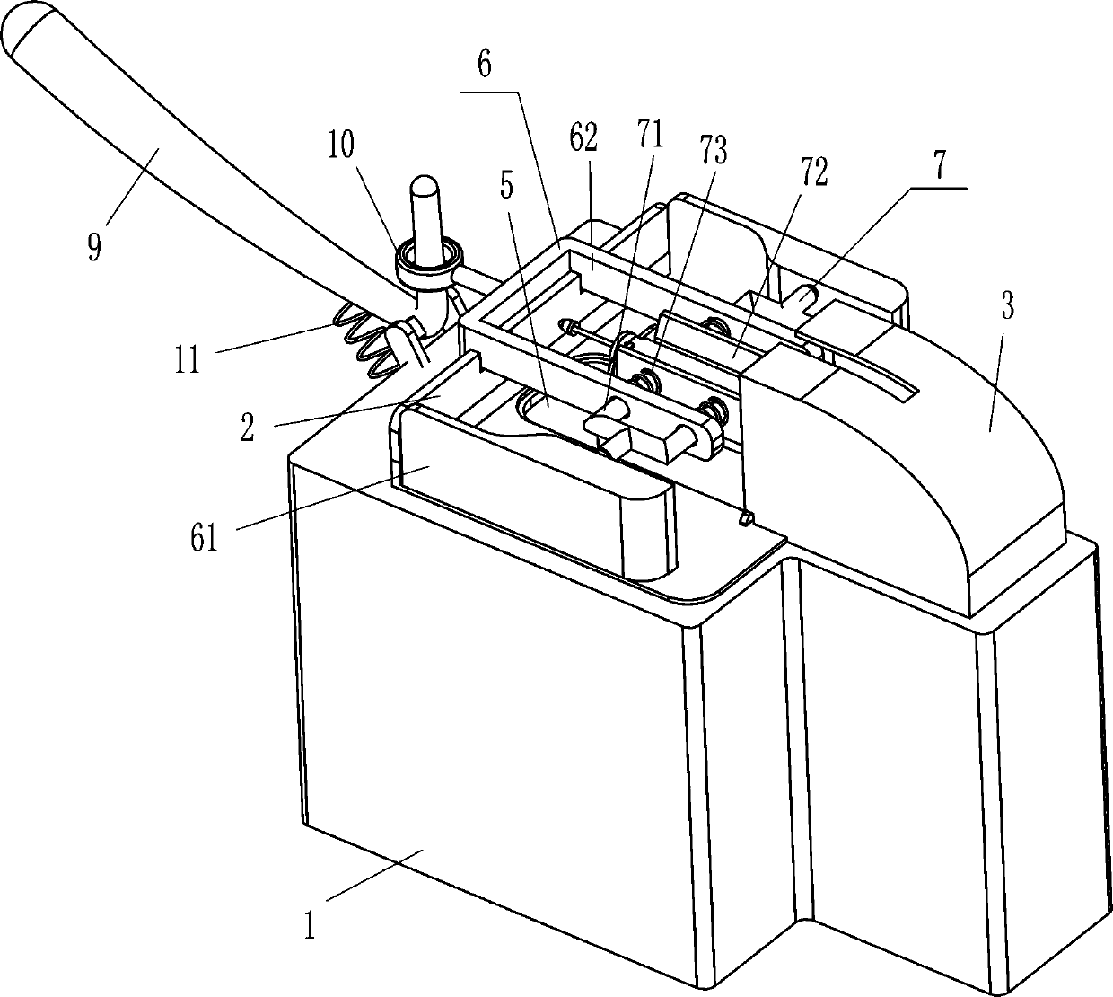
[0021] see figure 1 and figure 2 , a device for destroying syringes after use, including a box body 1, an L-shaped clamping plate 2, a housing 3, a partition plate 4, a driving mechanism 6 and a pressing mechanism 7, and the outer top of the box body 1 is clamped with an L-shaped clamping plate 2. A housing 3 is firmly connected to the middle of the inner bottom right side of the L-shaped card board 2, and the housing 3 is snap-connected with the outer top right side of the box body 1, and a partition plate 4 is fixedly connected to the right middle of the inner bottom of the box body 1, Type clamp 2 is provided with drive mechanism 6, and drive mechanism 6 is provided with compression mechanism 7 that can make syringe place, and compression mechanism 7 cooperates with drive mechanism 6, and L-shaped clamp 2 inner bottom middle is opened to make needle The through hole 5 through which the barrel passes, and the through hole 5 communicates with the inside of the box body 1 . ...

Embodiment 2

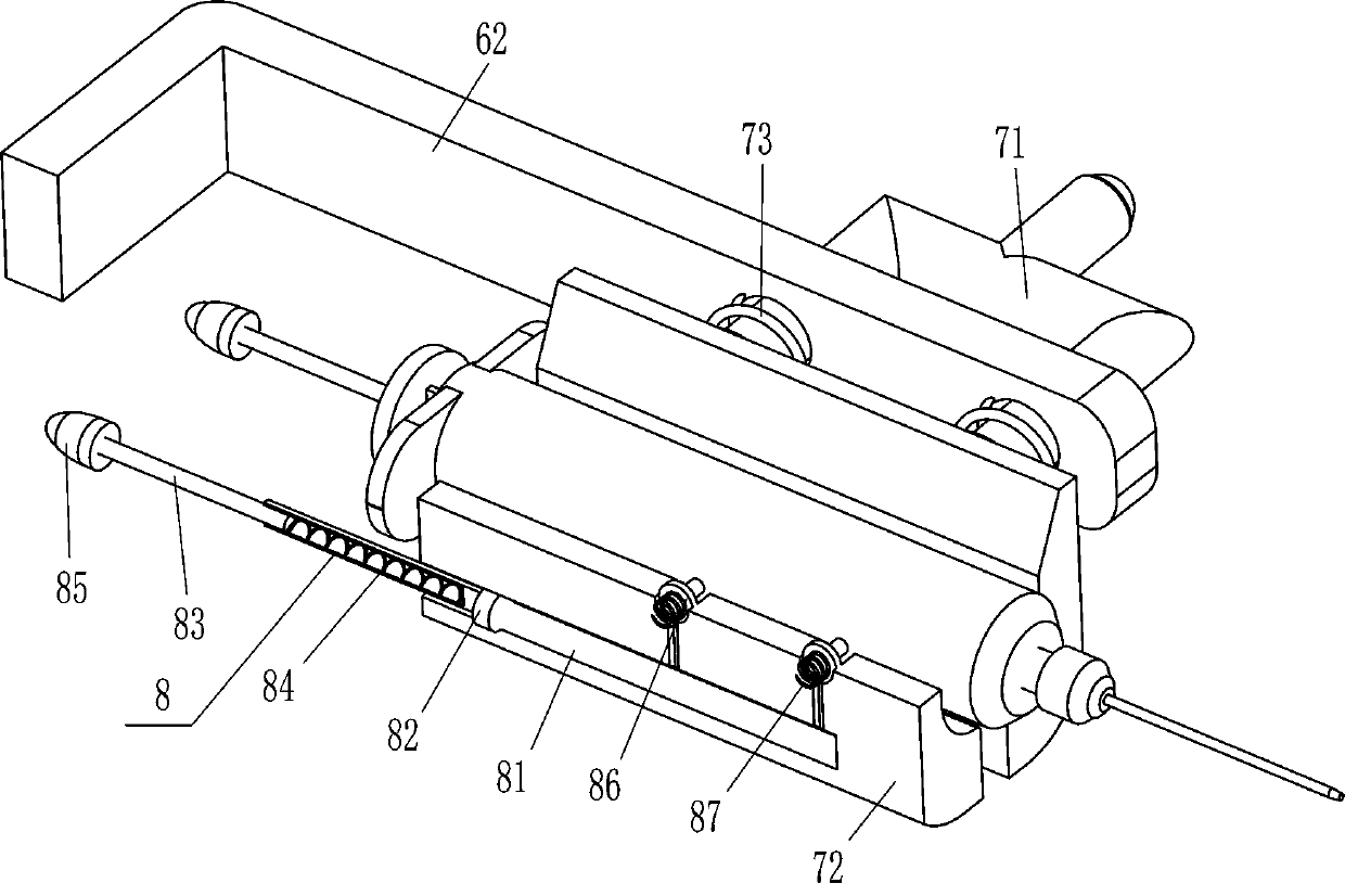
[0028] see image 3 Compared with Embodiment 1, the main difference of this embodiment is that in this embodiment, a destroying mechanism 8 is also included, and the destroying mechanism 8 includes a piston sleeve 82, a movable rod 83, a second spring 84, a ball seat 85, a piston Taper head 86 and the 3rd spring 87, special-shaped pressure plate 72 bottoms of front and back sides have special-shaped groove 81, and special-shaped groove 81 bottom left sliding type is provided with piston sleeve 82, and piston sleeve 82 inner sliding type is provided with Movable bar 83, movable bar 83 left ends are affixed with rolling ball seat 85, and rolling ball seat 85 cooperates with L-shaped clamping plate 2, and second spring 84 is connected between movable bar 83 right-hand sides and the inner right side of piston sleeve 82, The left and right sides of special-shaped groove 81 top are slidingly provided with the piston cone 86 that can destroy the syringe, and the third spring 87 is co...

Embodiment 3

[0031] see figure 1 and figure 2 The main difference between this embodiment and embodiment 1 and embodiment 2 is that in this embodiment, it also includes an L-shaped pull rod 9, a hanging ring 10 and a fourth spring 11, and the middle of the upper left side surface of the outer box body 1 is hinged with a L-shaped pull rod 9, a fourth spring 11 is connected between the right side of the inner bottom of the L-shaped pull rod 9 and the top of the outer left side of the box body 1, and a hanging ring 10 is fixedly connected to the middle of the outer left side of the u-shaped plate 62, and the hanging ring 10 Be enclosed within L-shaped tie rod 9 tops and cooperate with it.

[0032] After the syringe is placed, the left part of the L-shaped pull rod 9 is pulled to swing downward, the fourth spring 11 is compressed, the left part of the L-shaped pull rod 9 swings downward to make the upper part swing to the left, and the upper part of the L-shaped pull rod 9 swings to the left...


PUM


Abstract

The invention relates to a destroying device, in particular to a destroying device for used syringes. The destroying device for used syringes can crush the syringe and collect the syringe and a needlehead, and is convenient to operate and high in working efficiency. The destroying device for used syringes comprises a box body, an L-shaped clamping plate is connected to the outer side of an opening of the box body in a clamped mode, a through hole is formed in the side, close to the box body, of the L-shaped clamping plate, and the through hole is communicated with the interior of the box body. An injector is placed into the two special-shaped pressing plates, the discharging end of the needle cylinder is clamped into the clamping plate, the u-shaped plate is pulled to move leftwards, theneedle cylinder can move leftwards to be separated from the needle head, the separated needle cylinder and needle head fall into the left portion and the right portion in the box body respectively tobe collected, operation is convenient, and the working efficiency is high.

Description

technical field [0001] The invention relates to a destruction device, in particular to a destruction device for a syringe after use. Background technique [0002] A syringe is a common medical device. As early as the 15th century, the Italian Catinelle proposed the principle of the syringe. The gas or liquid is withdrawn or injected mainly with a needle. Syringes can also be used for medical equipment, containers, such as some scientific instruments in chromatography to inject through rubber diaphragms. Syringes are composed of syringes and needles. After the syringes are used, there will be germs on the syringes. Destroy the syringe to prevent the syringe from being reused by people and causing the spread of germs. [0003] Existing destructors, such as the Chinese patent whose patent notification number is CN202539168U discloses a syringe destructor, which relates to a processing device for discarded syringes. It includes a shell and a manual operating device, the shel...

Claims


Application Information

Patent Timeline
Patent Type & Authority Applications(China)
IPC IPC(8): A61M5/50A61M5/32
CPCA61M5/50A61M5/3278A61M2005/5006Y02W30/10
Inventor 不公告发明人
Owner NANJING HANXIYUE AUTOMATION TECH CO LTD
Why Eureka
Try Eureka