Shaping and edge cutting stamping die

A stamping die and edge trimming technology, which is applied in the field of shaping and trimming stamping dies, can solve the problems of high mold cost and low pass rate, and achieve the effects of low cost, improved pass rate, and stability

Inactive Publication Date: 2020-08-18
重庆捷尔博模具科技有限公司
View PDF10 Cites 2 Cited by
  • Summary
  • Abstract
  • Description
  • Claims
  • Application Information

AI Technical Summary

Problems solved by technology

[0003] The present invention intends to provide a shaping and trimming stamping die to solve the problems in the prior art that different stamping dies are used in the shaping and trimming process of sheet metal parts, resulting in high mold cost and low pass rate of sheet metal parts

Method used


Image

  • Shaping and edge cutting stamping die
  • Shaping and edge cutting stamping die
  • Shaping and edge cutting stamping die

Examples


Embodiment 1

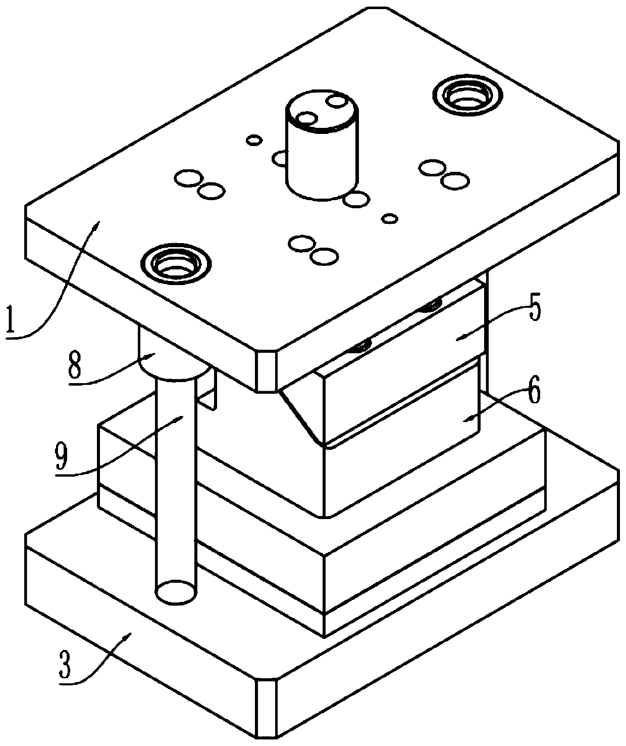
[0039] Embodiment one is basically as attached Figure 1 to Figure 5 Shown:

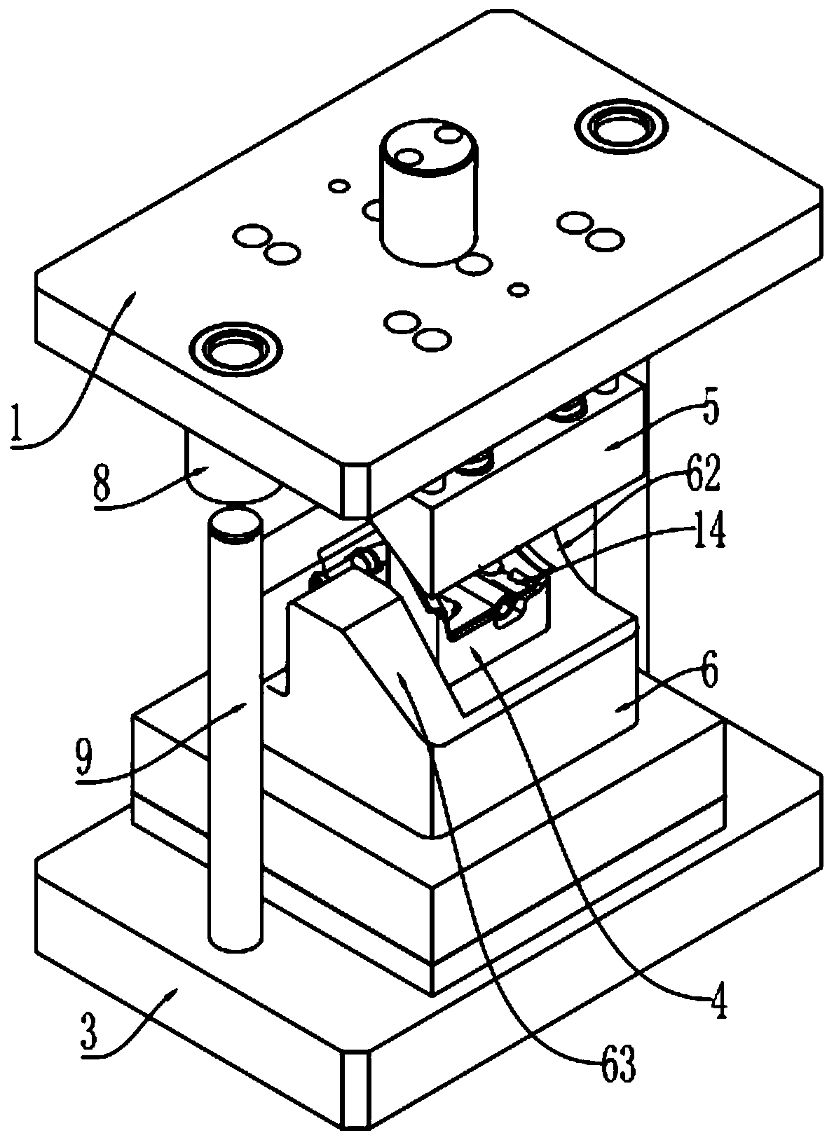
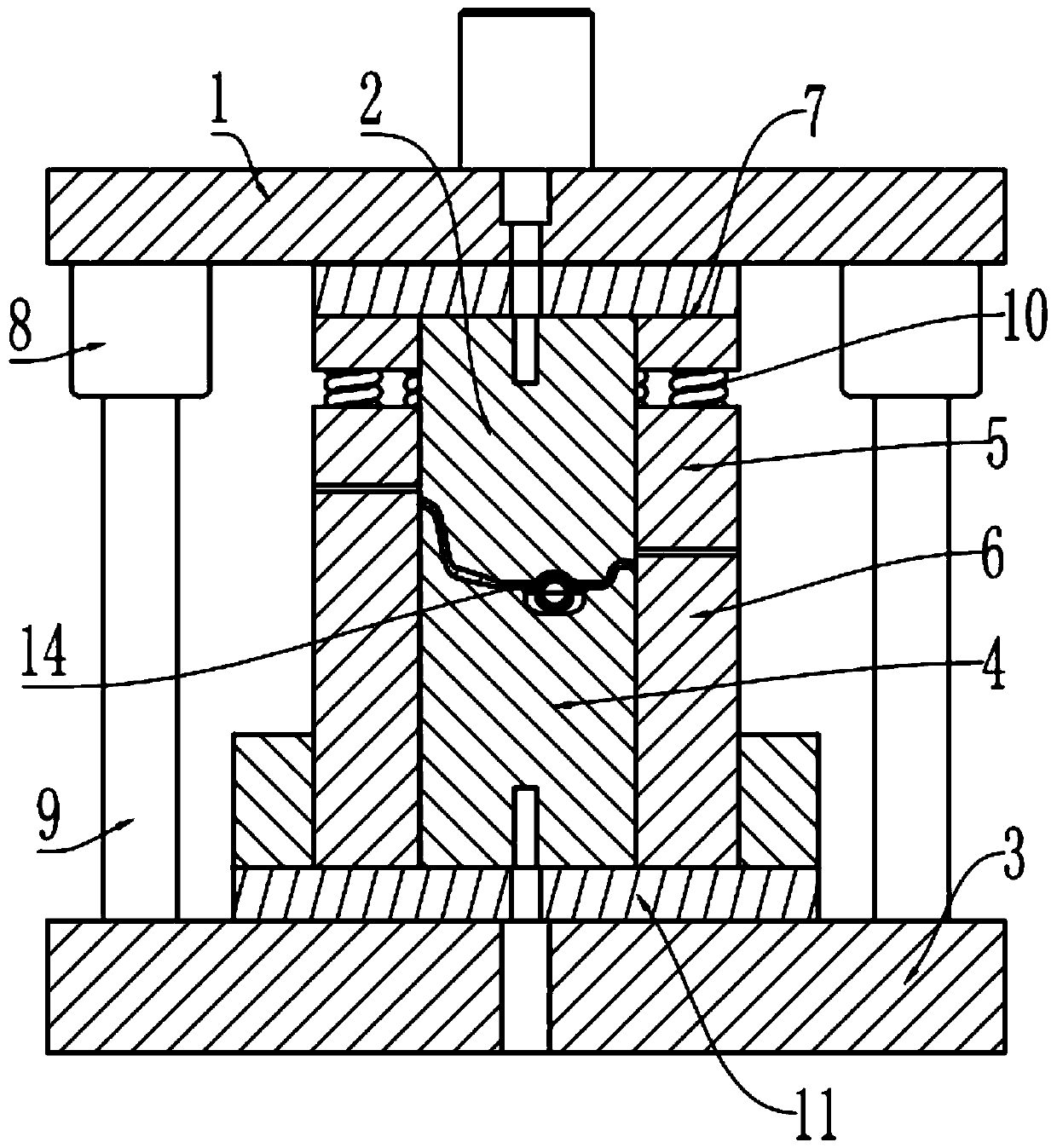
[0040] Stamping mold for shaping and trimming, including upper mold base 1, upper mold plate 2, lower mold base 3, lower mold plate 4, upper platen 5 and lower platen 6, upper platen 2 and upper mold base 1 are fixedly connected by bolts Plate 7, the upper mold base 1 is fixedly connected with a guide sleeve 8, the lower mold base 3 is fixedly connected with a guide post 9 that can be inserted into the guide sleeve 8, and the upper die base 1 can move vertically along the guide post 9; Pressing plate 5 is positioned at the bottom of upper backing plate 7, and vertical sliding connection is connected with connector 13 on the upper backing plate 7, and the lower end of connector 13 passes through upper backing plate 7 and is screwed on the upper pressing plate 5, and the upper end of connector 13 vertically Slidingly connected on the upper backing plate 7, the upper template 2 is set in the middle of ...

Embodiment 2

[0052] Embodiment two is basically as attached Figure 6 As shown, Embodiment 2 has made the following improvements on the basis of Embodiment 1: There is a horizontal chute in the lower formwork 4, and a push block 15 with a wedge surface is connected to the horizontal slide in the chute, and the wedge surface of the push block 15 Downward, the push block 15 can stick to the curved surface 62 on the lower pressing plate 6, and a third elastic member is welded between the push block 15 and the bottom of the chute, and the third elastic member adopts a spring.

[0053] The screw on the lower platen 6 is connected with a guide plate 16, and the guide plate 16 is provided with a guide groove. The end rests on the opening of the collection box 17.

[0054] The specific implementation process is as follows:

[0055] During the mold opening process of the upper template 2 and the lower template 4, the lower template 4 moves upward under the action of the second elastic member 12, ...


PUM


Abstract

The invention relates to the technical field of stamping forming and specifically discloses a shaping and edge cutting stamping die. The shaping and edge cutting stamping die comprises an upper die base, an upper die plate, a lower die base and a lower die plate. The upper die base can move vertically. The upper die plate is fixedly connected to the upper die base. The shaping and edge cutting stamping die further comprises an upper pressing plate and a lower pressing plate. First elastic parts are connected between the upper pressing plate and the upper die base. The lower pressing plate is fixedly connected to the lower die base. The lower pressing plate is internally provided with a cavity. The lower die plate is slidably connected to the interior of the cavity of the lower pressing plate. A second elastic part is arranged at the bottom of the lower die plate. Through the shaping and edge cutting stamping die, the problems that different stamping dies are adopted for shaping and edge cutting of sheet metal parts, the die cost of the sheet metal parts is high and the qualified rate is low in the prior art can be solved.

Description

technical field [0001] The invention relates to the technical field of stamping and forming, in particular to a stamping die for shaping and trimming. Background technique [0002] Stamping die is a special process equipment for processing metal or non-metallic materials into parts or semi-finished parts in cold stamping. In the prior art, it is popular because of its high structural strength after metal stamping. It is widely used in sheet metal stamping The forming process will involve punching and shearing (such as trimming), bending, stretching, shrinking, curling, shaping, etc. of sheet metal parts. The molds required for different types of processing are different, and the forming is different. The process needs to use different molds, such as the punching and shearing mold used in the stamping mold, a separate bending mold can be used for bending, drawing molds can be used for stretching, and forming molds can be used for curling and shrinking; especially for structur...

Claims


Application Information

Patent Timeline
Patent Type & Authority Applications(China)
IPC IPC(8): B21D37/10B21D1/00B21D28/02B21D28/14B21D43/00B21D43/20B21D45/02
CPCB21D1/00B21D28/02B21D28/14B21D37/10B21D43/003B21D43/20B21D45/02
Inventor 韦兴立
Owner 重庆捷尔博模具科技有限公司
Why Eureka
Try Eureka