Automatic feeding equipment for die stamping

A technology of feeding equipment and molds, which is applied in metal processing equipment, manufacturing tools, feeding devices, etc., can solve the problems of large coil material quality, time-consuming and labor-consuming, laborious and troublesome handling, and improve installation efficiency and handling efficiency , to avoid troublesome and laborious effects

Inactive Publication Date: 2020-08-18
衢州瑞展信息科技有限公司
View PDF9 Cites 3 Cited by
  • Summary
  • Abstract
  • Description
  • Claims
  • Application Information

AI Technical Summary

Problems solved by technology

[0002] The function of the metal coil material uncoiling and feeding equipment is to uncoil and level the metal coil material (strip steel, iron coil) and feed it to the machine tool of the subsequent processing procedure. A coil material feeding equipment is disclosed in the open document with the publication number CN205146927U , the feeding motor and gearbox can be reasonably arranged in the main frame, while the coiling shaft is arranged horizontally and driven by the transmission assembly, which effectively simplifies the overall structure, and is small in size, reduces the occupied space, and is easy to operate. The braking device performs braking and stopping. The whole operation process is simple, convenient, safe, low labor intensity and high work efficiency, which is conducive to wide application; however, after the device transports the coil material, the coil material Sometimes, there will be vibration, which will affect the stamping process, and it will not be able to effectively transport the coil material to the stamping table for stamping, which will greatly affect the stamping efficiency
[0003] There is a device that allows the coil material to be fixed easily and labor-saving, so as to facilitate the conveying and stamping of the coil material, which ensures the stability of the coil material during conveying, improves the conveying efficiency of the coil material, and can adjust the thickness of the coil material at the same time. Carry out self-adaptive adjustment to adapt to the thickness of the coil material efficiently and quickly, avoid the trouble of manual adjustment, effectively ensure the stability of the coil material conveying, very reliable and practical; It is very laborious and troublesome, and it is also very time-consuming and labor-intensive to install

Method used


Image

  • Automatic feeding equipment for die stamping
  • Automatic feeding equipment for die stamping
  • Automatic feeding equipment for die stamping

Examples


Embodiment Construction

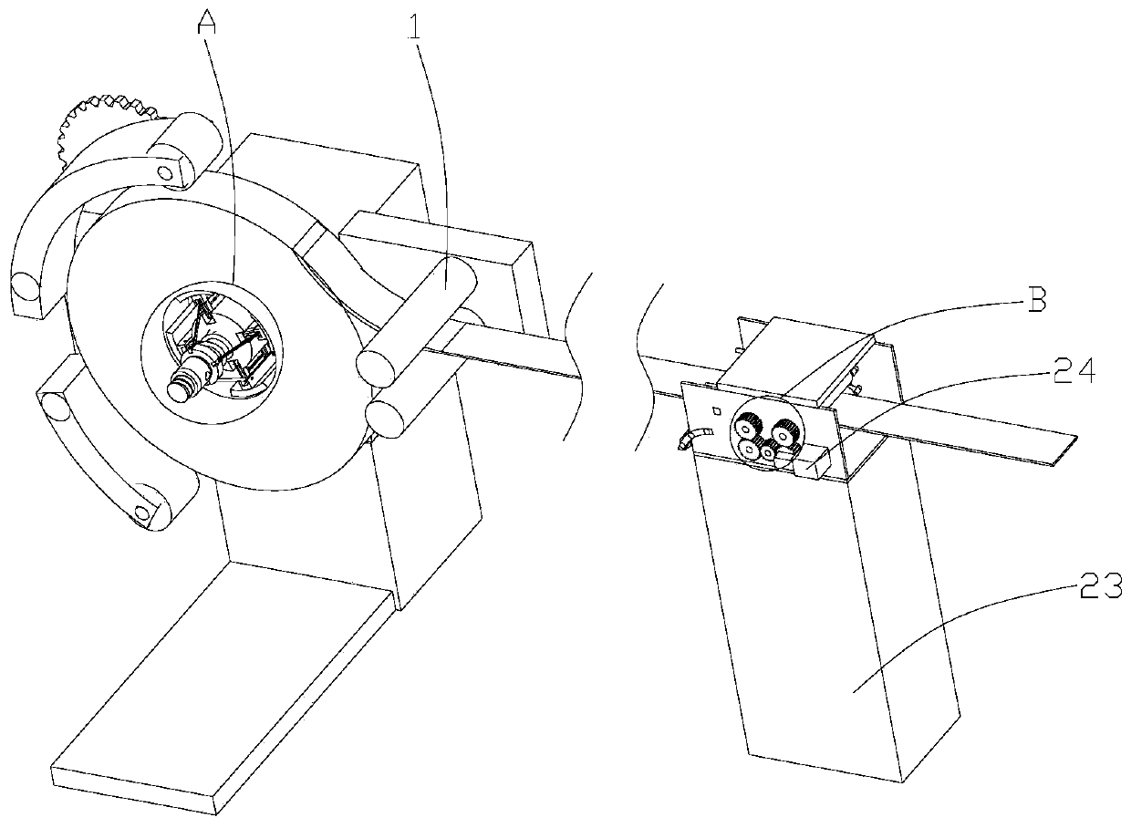
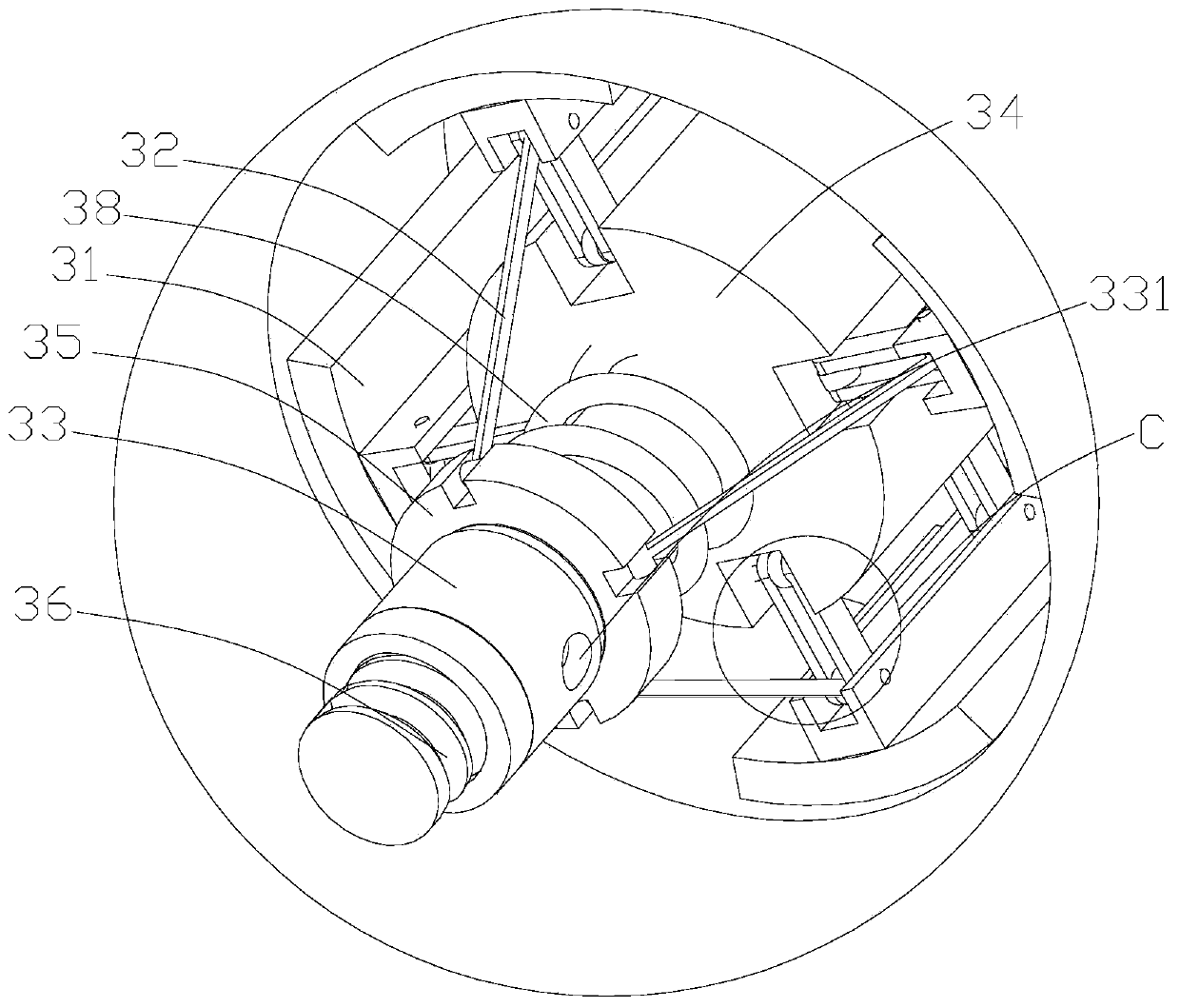
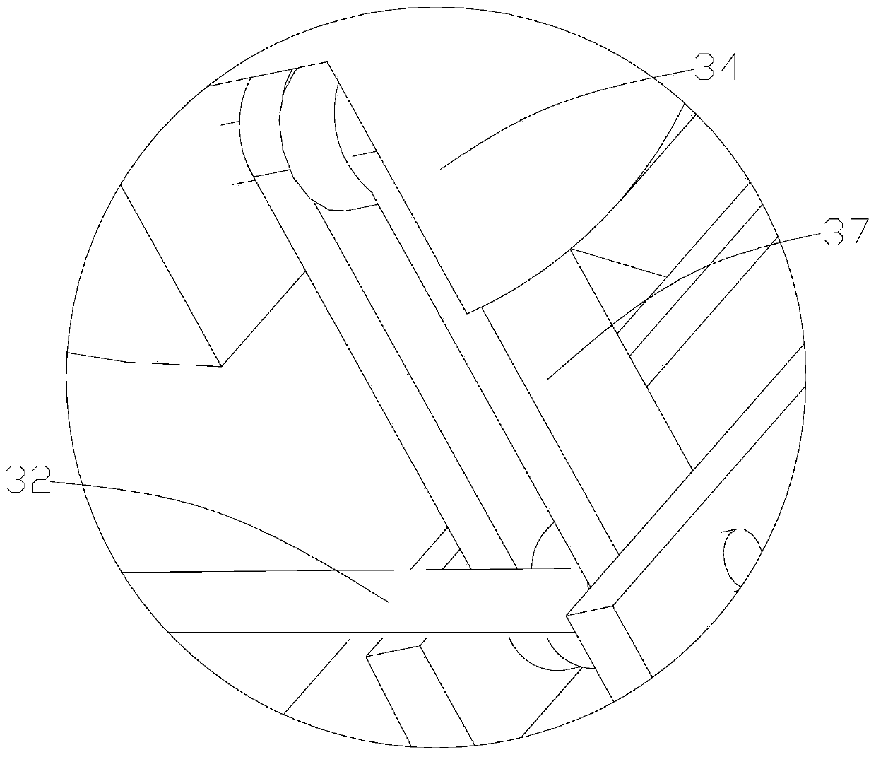
[0025] Such as Figure 1-12 As shown, a kind of automatic feeding equipment for mold stamping, including a fastening mechanism for conveying the coil material to be stamped, a guide roller group 1 for guiding and conveying one end of the coil material and for preventing The anti-throwing mechanism that the coil material is thrown out from the fixing mechanism after the coil material is about to be conveyed also includes a feeding mechanism for clamping and feeding the coil material. The first pinch roller 21 and the second pinch roller 22, the adjusting device for automatically adjusting the spacing of coil materials of different specifications, and the support base 23 for supporting the first pinch roller 21 and the second pinch roller 22 , through the setting of the above structure, the efficient and stable delivery of the coil material can be effectively realized, so that when the coil material is stamped, the coil material can be fixedly transported, and the shaking of the...


PUM


Abstract

The invention discloses automatic feeding equipment for die stamping. The automatic feeding equipment for die stamping comprises a feeding mechanism for clamping and feeding roll materials, wherein the feeding mechanism comprises a plurality of first clamping rollers and second clamping rollers for clamping and fixing the roll materials, and an adjusting device for automatically adjusting the distances between the roll materials of different specifications. The automatic feeding equipment for die stamping also comprises a supporting seat used for supporting the roll materials, a driving deviceused for driving the supporting seat to do lifting motion, and a movable base used for allowing the supporting seat to transversely move; through the arrangement of the structure, the supporting seatcan fixedly install the roll materials to be conveyed, the moving effect of the roll materials can be achieved through control of the driving device and the movable base, and the carrying and installing efficiency of the roll materials is effectively improved.

Description

technical field [0001] The invention belongs to the technical field of coil material conveying, and in particular relates to an automatic material feeding device for die stamping. Background technique [0002] The function of the metal coil material uncoiling and feeding equipment is to uncoil and level the metal coil material (strip steel, iron coil) and feed it to the machine tool of the subsequent processing procedure. A coil material feeding equipment is disclosed in the open document with the publication number CN205146927U , the feeding motor and gearbox can be reasonably arranged in the main frame, while the coiling shaft is arranged horizontally and driven by the transmission assembly, which effectively simplifies the overall structure, and is small in size, reduces the occupied space, and is easy to operate. The brake device performs braking and stopping. The whole operation process is simple, convenient, safe, low labor intensity, high work efficiency, and is condu...

Claims


Application Information

Patent Timeline
Patent Type & Authority Applications(China)
IPC IPC(8): B21D43/02B21D43/09B21C47/18B21C47/26B21C47/28B21C47/34
CPCB21C47/18B21C47/26B21C47/28B21C47/34B21D43/02B21D43/09
Inventor 吴文君
Owner 衢州瑞展信息科技有限公司
Why Eureka
Try Eureka