
Mounting configuration for exhaust pipe cover of engine

A technology of exhaust pipe cover and installation structure, which is applied in the direction of exhaust devices, engine components, machines/engines, etc., which can solve problems such as vibration, weakened isolation function, and cover cannot be firmly supported, and achieve the effect of less parts

Inactive Publication Date: 2003-07-23
MITSUBISHI HEAVY IND LTD
View PDF0 Cites 0 Cited by
  • Summary
  • Abstract
  • Description
  • Claims
  • Application Information

AI Technical Summary

Problems solved by technology

This means that the cover is also prone to reaching a high temperature and its basic insulating function is weakened
[0009] Also, the technique explained above requires special components such as mounting joints, which increases the number of parts and the production steps for manufacturing the mounting base.
[0010] Like the prior art, the design disclosed in Japanese Utility Model Publication (Kokai) 62-185833 also requires special parts such as bolts to install the exhaust pipe cover, this bolt is only used to install the pipe, At the same time this also leads to an increase in the number of parts
In addition to this disadvantage, the lower part of the hood is fixed with the lower hood cover, which is made of a plate that is not very strong, so that the hood cannot be firmly supported, causing vibrations and noise

Method used


Image

  • Mounting configuration for exhaust pipe cover of engine
  • Mounting configuration for exhaust pipe cover of engine
  • Mounting configuration for exhaust pipe cover of engine

Examples


Embodiment Construction

[0020] The present invention will be explained in detail below with reference to the preferred embodiments for the purpose of illustration with reference to the accompanying drawings. The relevant dimensions, materials, shapes and parts described in these embodiments do not need to be fixed exactly, so the scope of the present invention Without being limited to the embodiments described herein, these embodiments are provided by way of example only.

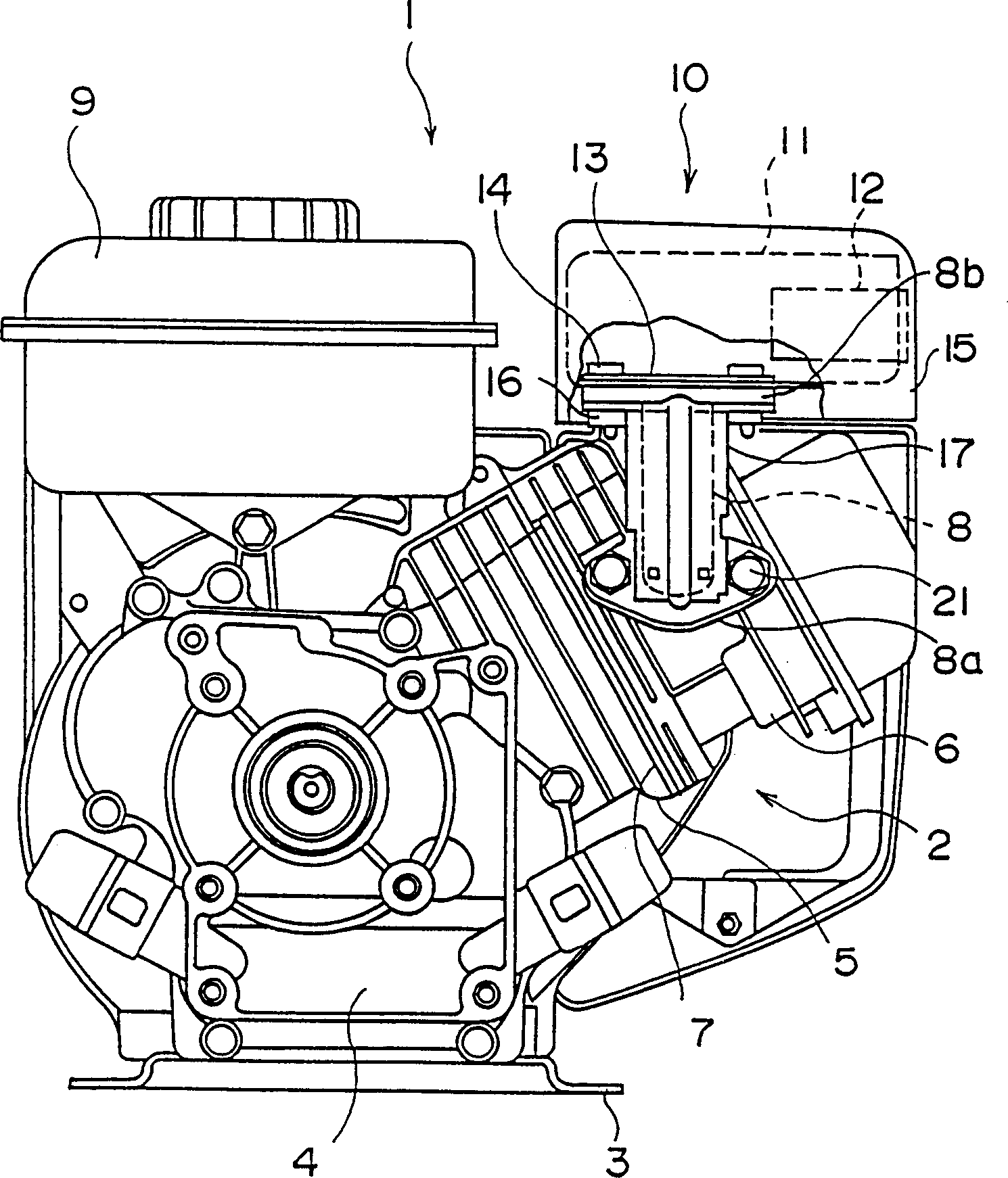
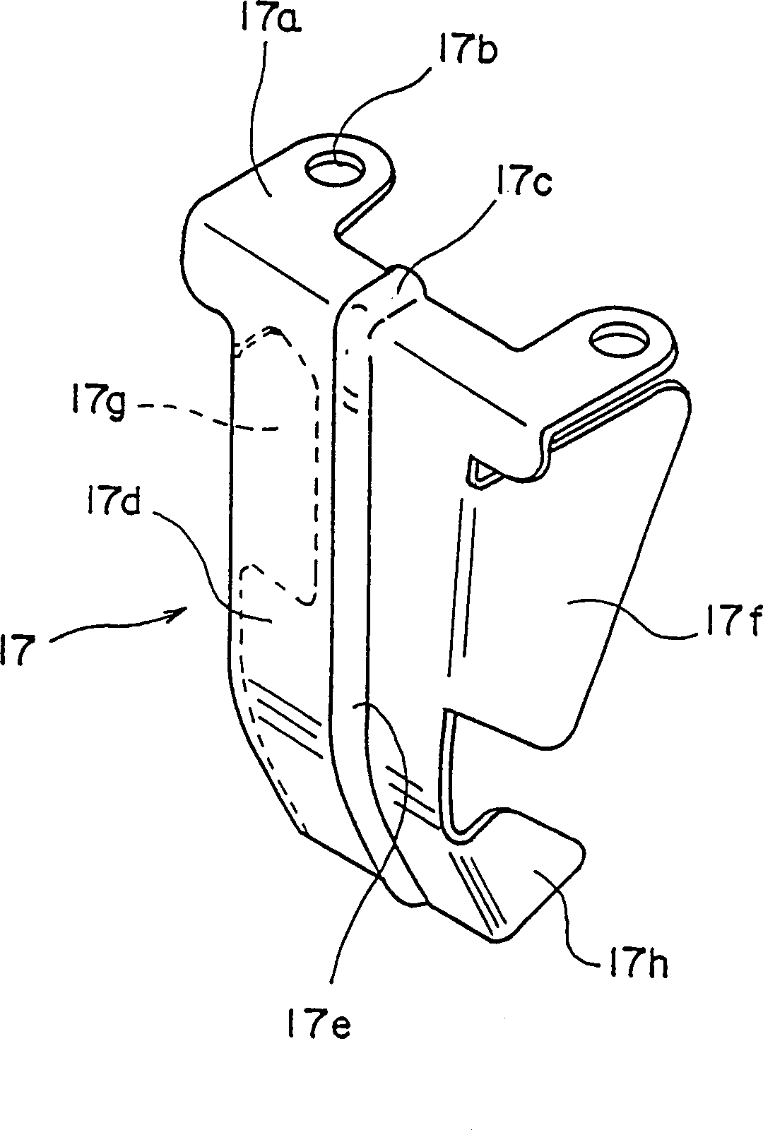
[0021] figure 1 It is a front view of a small multi-purpose single-cylinder engine as a preferred embodiment of the present invention. figure 2 is a plan view of the engine. image 3 It is a perspective view of the outside of the engine exhaust pipe cover.

[0022] exist figure 1 and 2 In , the reference numeral 1 represents a single-cylinder engine in which a cylinder is inclined upward. Reference numeral 2 denotes a cylinder body, which is installed and fixed on a pedestal 3 . The engine mainly includes a crankcase 4, a c...


PUM


Abstract

A mounting configuration for an exhaust pipe cover of an engine, a muffler is affixed to an outlet flange of an exhaust pipe whose inlet flange is connected to an exhaust outlet of a cylinder head of the engine. The exhaust pipe cover is affixed with the muffler to the outlet flange of the exhaust pipe. An upper flange of the exhaust pipe cover is affixed to both the bottom of the muffler and the outlet flange of the exhaust pipe, and a front portion of the exhaust pipe cover extends downward from the upper flange in such a way as to cover the exhaust pipe. This configuration reduces the number of parts and of production and assembly processes, and lowers the cost, and it reliably insulates the exhaust pipe without resulting in vibration and provides a secure mounting for the cover.

Description

technical field [0001] The invention relates to a mounting structure for an external isolation cover of an exhaust pipe of a small multi-purpose single-cylinder engine. Background technique [0002] In recent years, small utility engines have been improved to be lighter in overall weight and more compact to the point where they can be picked up and carried by hand. At the same time, various designs have been proposed for the shielding of the exhaust pipe, which becomes particularly hot when the engine is running. [0003] In the prior art, this type of exhaust pipe cover is installed on the engine using the following structure. [0004] (1) When using an exhaust pipe made of steel pipe, the exhaust pipe cover may be welded to the exhaust pipe to form a unitary structure, or the mounting joint may be welded to the exhaust pipe and bolted or similar hardware Fasten the shroud to the fitting so there is a gap between the tube and the shroud. [0005] (2) When using an exhaus...

Claims


Application Information

Patent Timeline
IPC IPC(8): F01N13/14F02B77/11
CPCF01N13/14F01N2590/06F01N13/002F01N13/1855
Inventor 河内弘吉小林和之中村彰吾
Owner MITSUBISHI HEAVY IND LTD
Features
  • Generate Ideas
  • Intellectual Property
  • Life Sciences
  • Materials
  • Tech Scout
  • Unparalleled Data Quality
  • Higher Quality Content
  • 60% Fewer Hallucinations
Learn More