Tail rotor pitch control shaft device and preparation method thereof

A technology for manipulating shafts and pitches, which is applied to aircraft transmissions, aircraft power units, propellers, etc., can solve problems such as wear structure, deformation, and reduced service life of parts, so as to prolong service life, reduce wear or overheating, and reduce misalignment effect

Active Publication Date: 2021-12-24
AECC HUNAN AVIATION POWERPLANT RES INST
View PDF14 Cites 0 Cited by
  • Summary
  • Abstract
  • Description
  • Claims
  • Application Information

AI Technical Summary

Problems solved by technology

[0003] The invention provides a tail rotor pitch control shaft device and a preparation method thereof to solve the technical problems that the existing tail rotor pitch control shaft moves frequently, easily causes structural deformation due to wear, and reduces the service life of parts

Method used


Image

  • Tail rotor pitch control shaft device and preparation method thereof
  • Tail rotor pitch control shaft device and preparation method thereof
  • Tail rotor pitch control shaft device and preparation method thereof

Examples


Embodiment Construction

[0029] It should be noted that, in the case of no conflict, the embodiments in the present application and the features in the embodiments can be combined with each other. The present invention will be described in detail below with reference to the accompanying drawings and examples.

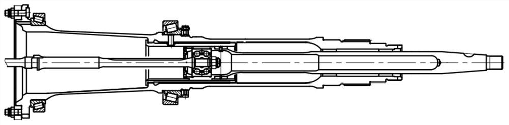
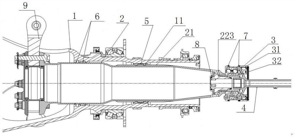
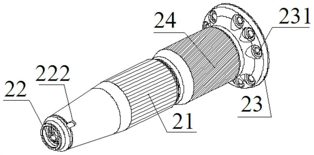
[0030] figure 1 is the schematic diagram of the existing tail rotor pitch control shaft; figure 2 is a schematic diagram of a tail rotor pitch control shaft device in a preferred embodiment of the present invention; image 3 is a schematic diagram of the pitch control shaft in a preferred embodiment of the present invention; Figure 4 It is the left side view of the pitch control shaft of the preferred embodiment of the present invention.

[0031] Such as figure 2 with image 3 As shown, the tail rotor pitch control shaft device of this embodiment includes: a tail rotor shaft 1, which is used to cooperate with the inner spline 11 of the tail rotor shaft 1 and to be connected along the ax...


PUM


Abstract

The invention discloses a tail rotor pitch control shaft device and a preparation method thereof, comprising: a tail rotor shaft, a pitch control shaft, and the pitch control shaft is provided with a guiding outer spline for cooperating with an inner spline of the tail rotor shaft , the booster joystick, the support assembly, the support assembly includes a first support, a second support and a third support; the first support includes a first sliding sleeve sleeved on the guide outer spline; the second support includes The second sliding sleeve and the square ring are sleeved on the end of the pitch control shaft away from the booster control rod; the third support includes a piston that is used to cooperate with the inner hole of the reducer casing and is installed on the bearing bush of the bearing sealing ring. The tail rotor pitch control shaft device of the present invention adopts three-point support to ensure the smooth control movement of the pitch control shaft, reduce the misalignment between the pitch control shaft and the control rod of the tail rotor booster, and reduce the bending caused by eccentric loads. Torque, reduce pitch control shaft and bearing wear or overheating and other faults.

Description

technical field [0001] The invention relates to the field of helicopter tail reducers, in particular to a tail rotor pitch control shaft device. In addition, the present invention also relates to a preparation method of the tail rotor pitch control shaft device. Background technique [0002] The tail rotor pitch control shaft of the helicopter tail reducer is built in the tail rotor shaft, reciprocates along the axis, and controls the key part of the tail rotor blade pitch change. The conventional typical structure is as follows: figure 1 As shown, the tail rotor pitch control shaft built in the tail rotor shaft is pushed back and forth axially by the control rod of the tail rotor booster, and the guide key of the tail rotor pitch control shaft reciprocates axially along the guide groove of the guide cylinder , to realize the variable pitch of the tail rotor blade. The guide cylinder is generally made of aluminum, and the guide key of the tail rotor pitch control shaft rec...

Claims


Application Information

Patent Timeline
Patent Type & Authority Patents(China)
IPC IPC(8): B64D35/00B64C11/32B64C13/30
CPCB64D35/00B64C11/32B64C13/30
Inventor 潘文斌吴红美艾永生陈金张川
Owner AECC HUNAN AVIATION POWERPLANT RES INST
Why Eureka
Try Eureka