Automatic centering platform

An automatic centering and platform technology, applied in the direction of bolting devices, aircraft parts, ground devices, etc., can solve the problems of unmanned aerial vehicle position calibration, damage, long preparation time, etc.

Pending Publication Date: 2020-08-18
上海芝松航空科技有限公司
0 Cites 1 Cited by

AI-Extracted Technical Summary

Problems solved by technology

However, the lack of intelligent hangar carriers currently causes the following problems in the use of UAVs: (1) Professional pilots are required to carry them with them, with few personnel, different levels, and high commissions; limited backup energy cannot meet continuous Cruising; (2) The UAV is carried back and forth, there is a risk of damage...

Method used

Further improved, as shown in Figure 1-3: 2 longitudinal motors 8 that longitudinal sliding table group 2 comprises, start 2 longitudinal motors 8 and make it run synchronously, drive 2 sets of positive and negative synchronous drive mechanisms, respectively Push 2 pairs of sliders to drive a pair of longitudinal beams 3 to move synchronously, at constant speed, and in parallel to each other, so as to facilitate the promotion of the U...

Abstract

The invention discloses an automatic centering platform. The automatic centering platform comprises a parking platform, an automatic centering device and a beacon, the automatic centering device is arranged on the parking platform; the beacon is arranged in the center of the upper surface of the parking platform; and the automatic centering device comprises a longitudinal sliding table set, a longitudinal beam, a cross beam and a transverse sliding table set. The longitudinal sliding table set comprises two linear sliding tables which are transversely distributed and installed in parallel. Each linear sliding table comprises a longitudinal motor, a forward and reverse synchronous driving mechanism and two sliding blocks, the two sliding blocks are symmetrically arranged at the front end and the reverse end of the forward and reverse synchronous driving mechanism respectively and meshed with each other, the symmetry center is consistent with the center of the parking platform in the direction, and a longitudinal beam is arranged on the two sliding blocks on the same side of the two linear sliding tables. After the unmanned aerial vehicle lands on the parking platform, the unmanned aerial vehicle can be pushed by combining the longitudinal sliding tables with the transverse sliding table set, so that the unmanned aerial vehicle is parked in the middle of the parking platform, andautomatic centering is achieved.

Application Domain

Anchoring installationsLanding aids

Technology Topic

Electric machineryStructural engineering +3

Image

  • Automatic centering platform
  • Automatic centering platform
  • Automatic centering platform

Examples

  • Experimental program(1)

Example Embodiment

[0020] The following will clearly and completely describe the technical solutions in the embodiments of the present invention with reference to the accompanying drawings in the embodiments of the present invention. Obviously, the described embodiments are only some, not all, embodiments of the present invention. Based on the embodiments of the present invention, all other embodiments obtained by persons of ordinary skill in the art without making creative efforts belong to the protection scope of the present invention.
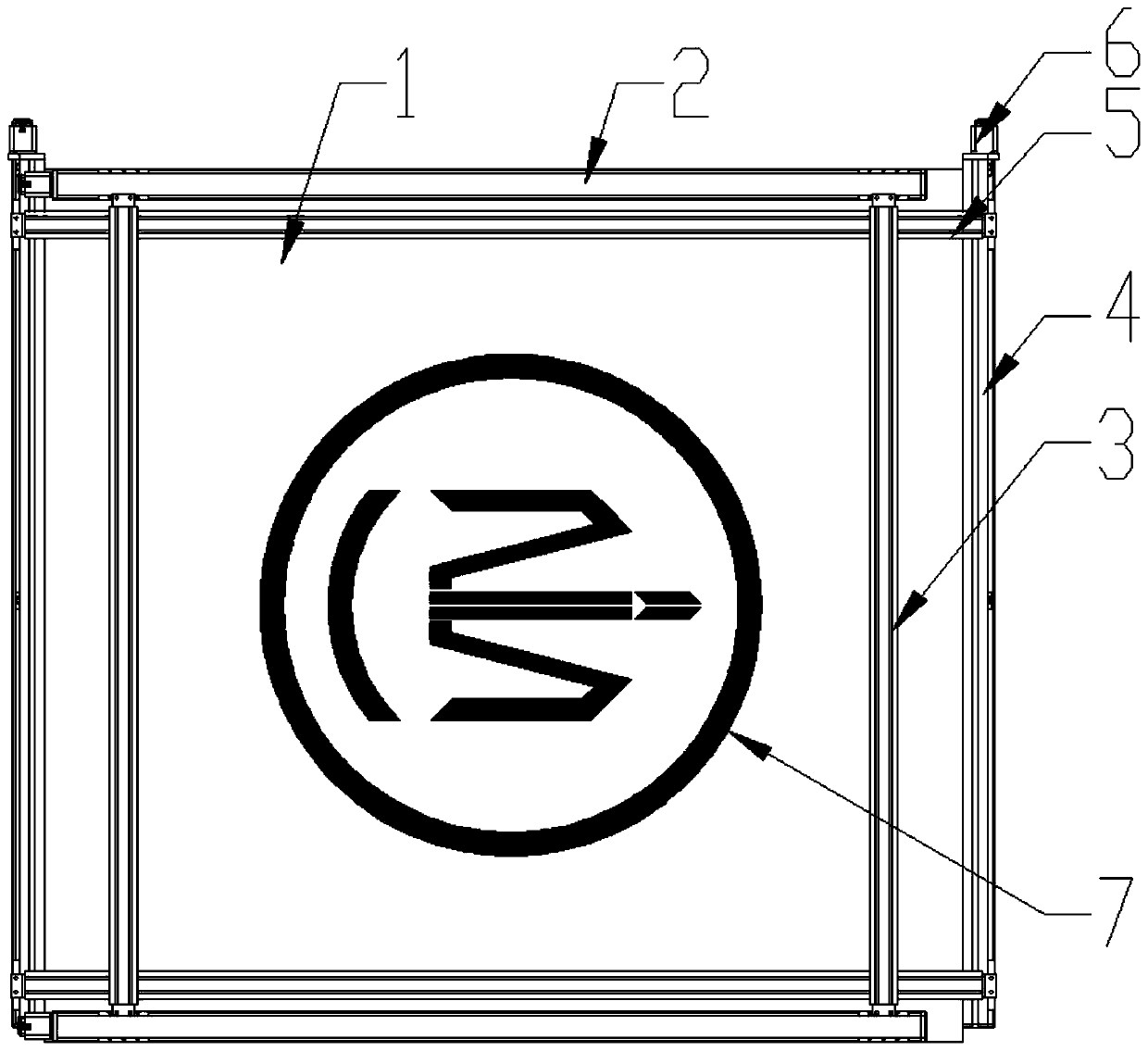
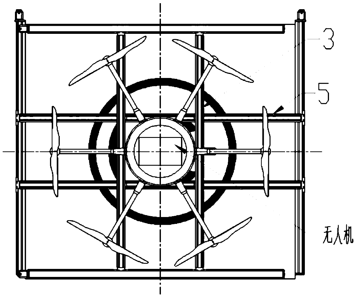
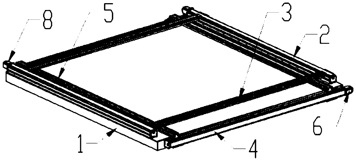
[0021] see Figure 1-4 , the present invention provides a technical solution: an automatic centering platform, comprising: a parking platform 1, an automatic centering device and a beacon 7, the automatic centering device is arranged on the parking platform 1, and the center of the upper surface of the parking platform 1 is provided with Beacon 7, which is convenient for viewing the position of the drone to the parking platform 1 when the drone lands. The automatic centering device includes a longitudinal slide group 2, a longitudinal beam 3, a beam 5, and a transverse slide set 4. The longitudinal slide Group 2 includes two horizontally distributed linear slides installed in parallel, each linear slide includes a longitudinal motor 8, a set of forward and reverse synchronous drive mechanisms and 2 sliders, and the 2 sliders are symmetrically arranged on the front The positive and negative ends of the reverse synchronous drive mechanism are meshed. The center of symmetry is consistent with the center of the parking platform 1 in this direction. The two sliders on the same side of the two linear slides are provided with a longitudinal beam 3, and the horizontal slide Group 4 includes two longitudinally distributed linear slides installed in parallel. Each linear slide includes a horizontal motor 6, a set of left and right synchronous drive mechanisms and 2 sliding blocks, and the 2 sliding blocks are symmetrically arranged in the left and right directions. The left and right ends of the synchronous drive mechanism are meshed. The center of symmetry is consistent with the center of the parking platform 1 in this direction. The two sliding blocks on the same side of the two linear slides are provided with a crossbeam 5, the horizontal slide group 4 and the longitudinal The slide group 2 adjusts the horizontal position and the longitudinal position of the UAV respectively, so that the UAV is automatically placed in the middle of the parking platform.
[0022] further improved, such as image 3 As shown: the longitudinal sliding table group 2 includes 2 longitudinal beams 3 arranged in parallel, and the 2 longitudinal beams 3 are symmetrical to the center of the parking platform 1, and the horizontal sliding table group 4 includes 2 parallel beams 5, and the 2 beams 5 are about The center of the platform 1 is symmetrical, and drives two longitudinal beams 3 or two cross beams 5 at the same time to calibrate the position of the drone. The longitudinal sliding table group 2 and the horizontal sliding table group 4 are vertically arranged in staggered layers.
[0023] further improved, such as Figure 1-3 As shown: the two longitudinal motors 8 included in the longitudinal slide group 2, start the two longitudinal motors 8 to make them run synchronously, drive 2 sets of forward and reverse synchronous drive mechanisms, respectively push 2 pairs of sliders, and drive a pair of longitudinal beams 3 Synchronous, constant speed, and parallel motion are convenient for driving the UAV.
[0024] further improved, such as Figure 1-3 As shown: the transverse sliding table group 4 includes two transverse motors 6, start the two transverse motors 6 to make them run synchronously, drive two sets of left and right synchronous drive mechanisms, respectively push two pairs of sliding blocks, and drive a pair of beams 5 synchronously, etc. Speed, relative to parallel movement, easy to push the UAV.
[0025] further improved, such as image 3 Shown: horizontal motor 6 and vertical motor 8 are a kind of in stepping motor or servo motor.
[0026] further improved, such as Figure 1-2 As shown: a position and direction beacon 7 that can be recognized by the UAV is set in the center of the parking platform 1. The beacon 7 can guide the UAV to make a precise landing on the parking platform 1 at close range, and play a guiding role in the parking of the UAV. .
[0027] Specifically, the beacon 7 may be a combination of a pattern and a Bluetooth sensor, a combination of a pattern and an infrared sensor, a combination of a pattern and a laser sensor, or a combination of a pattern and a visual sensor.
[0028] When the present invention is in use, the UAV is parked on the parking platform 1, and then the horizontal sliding table group 4 and the longitudinal sliding table group 2 are started, and the horizontal/longitudinal motors in the horizontal sliding table group 4 and the longitudinal sliding table group 2 rotate, Drive 2 sets of forward and reverse synchronous drive mechanisms, respectively push 2 pairs of sliders, drive a pair of longitudinal beams 3/beams 5 to move synchronously, at constant speed, and in parallel to each other, so as to push the UAV to automatically calibrate to the parking platform the middle position.
[0029] Finally, it should be noted that: the above is only a preferred embodiment of the present invention, and is not intended to limit the present invention. Although the present invention has been described in detail with reference to the foregoing embodiments, for those skilled in the art, it still The technical solutions recorded in the foregoing embodiments may be modified, or some technical features thereof may be equivalently replaced. Any modifications, equivalent replacements, improvements, etc. made within the spirit and principles of the present invention shall be included within the protection scope of the present invention.

PUM

no PUM

Description & Claims & Application Information

We can also present the details of the Description, Claims and Application information to help users get a comprehensive understanding of the technical details of the patent, such as background art, summary of invention, brief description of drawings, description of embodiments, and other original content. On the other hand, users can also determine the specific scope of protection of the technology through the list of claims; as well as understand the changes in the life cycle of the technology with the presentation of the patent timeline. Login to view more.
Why Eureka
Try Eureka