
Combing machine with rotary positioning driving device

A technology of positioning drive and combing machine, applied in the field of combing machine, can solve the problems of poor winding effect, disordered winding of sliver, low winding efficiency, etc. handy effect

Inactive Publication Date: 2020-08-18
刘美红
View PDF9 Cites 0 Cited by
  • Summary
  • Abstract
  • Description
  • Claims
  • Application Information

AI Technical Summary

Problems solved by technology

The combing machine device in the above-mentioned patent has the following disadvantages: after the cotton sliver is combed, there is no winding mechanism after the cotton sliver is output, and manual winding is required, the winding efficiency is low, and the winding of the cotton sliver is messy, and the winding is messy. The collection effect is not good, so there is still the problem that the sliver cannot be automatically rolled up

Method used

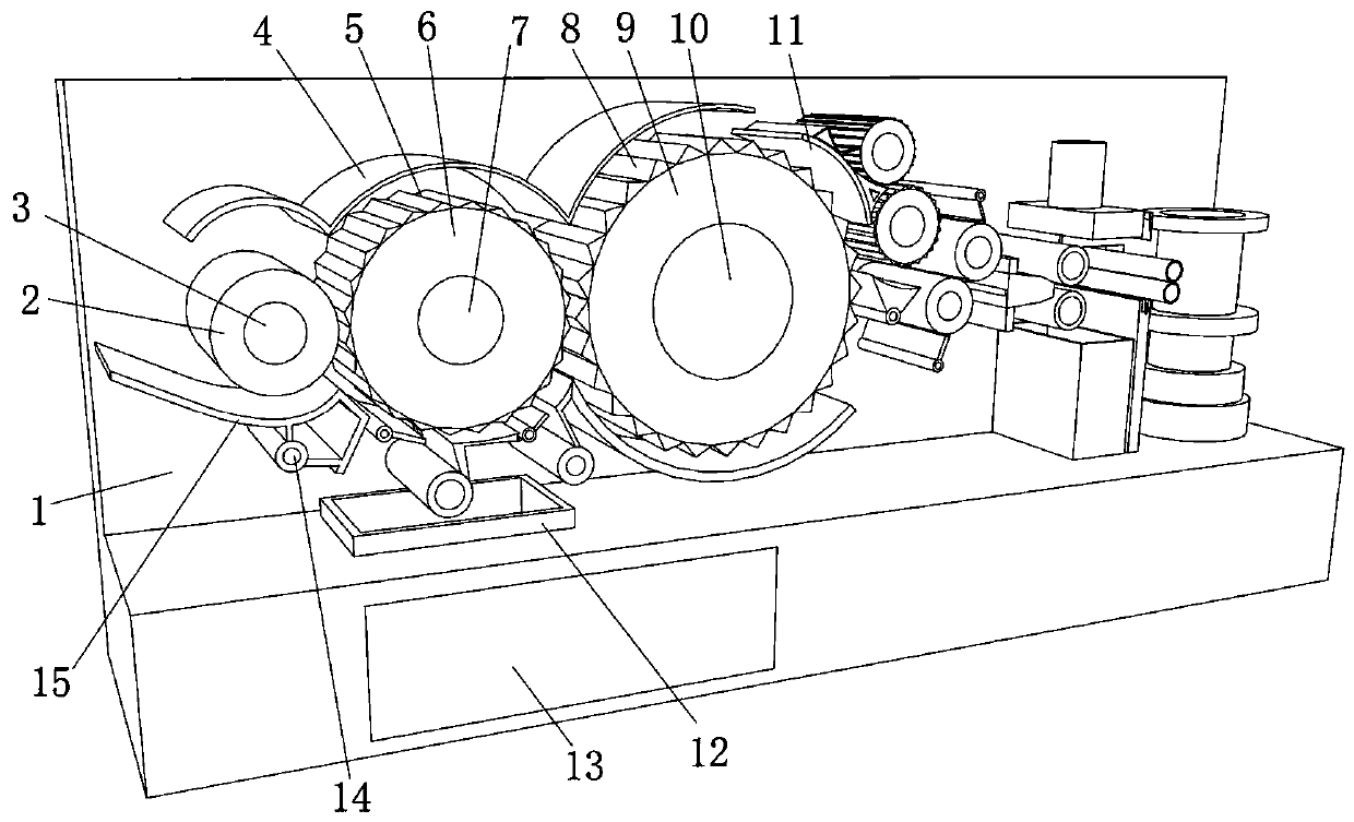
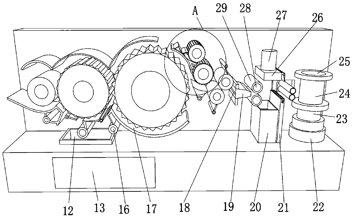
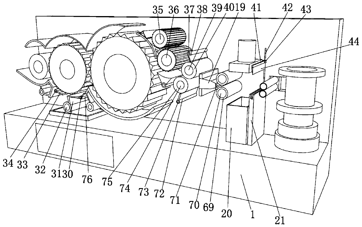

Image

  • Combing machine with rotary positioning driving device
  • Combing machine with rotary positioning driving device
  • Combing machine with rotary positioning driving device

Examples


Embodiment 1

[0035] A combing machine with rotary positioning drive, such as figure 1 , figure 2 and image 3 As shown, it includes a housing 1, the top outer wall of the housing 1 is fixed with a telescopic column 22 by screws, the top outer wall of the telescopic column 22 is fixed with a first drive motor 23, and the output end of the first drive motor 23 is passed through a coupling Connected with a fixed shaft 25, the outer wall of the fixed shaft 25 is fixed with a take-up disk 24 by screws, and the outer wall of one side of the shell 1 is fixed with a bell mouth 19 by screws, and the outer wall of one side of the bell mouth 19 is provided with a cotton inlet 18, and the bell mouth The outer wall of the other side of 19 has a cotton outlet 71, and the inside of the telescopic column 22 is fixed with a pneumatic tappet by screws; The cotton sliver output by 71 is rolled up, and the height adjustment is carried out through the telescopic column 22, which can make the rolling up of t...

Embodiment 2

[0041] A combing machine with rotary positioning drive, such as figure 1 , figure 2 , image 3 , Figure 4 As shown, in order to solve the problem of absorbing sundries; this embodiment makes the following improvements on the basis of embodiment 1: a collection chamber 45 is opened at the bottom of the housing 1, and a door 13 is fixed to the outer wall of one side of the collection chamber 45 by screws , the top outer wall of the housing 1 is fixed with a suction pipe 12 by screws, the top inner wall of the collection chamber 45 is fixed with a connecting pipe 47 by screws, the other end of the connecting pipe 47 is fixed with an exhaust fan 48 by screws, and one side of the outer wall of the connecting pipe 47 A filter plate 46 is plugged in, and the top outer wall of the collection chamber 45 is fixed with a third drive motor 49 by screws, and the output end of the third drive motor 49 is connected to a connecting shaft 50 through a coupling, and the peripheral outer wal...


PUM


Abstract

The invention discloses a combing machine with a rotary positioning driving device, and relates to the technical field of sliver processing. The combing machine with the rotary positioning driving device is used for solving the problem of incapability of automatically winding up slivers. Specifically, a shell is included, and a telescopic column is fixed to the outer wall of the top of the shell by screws. A first drive motor is fixed to the outer wall of the top of the telescopic column by screws. The output end of the first drive motor is connected with a fixed shaft through a coupling, a winding disc is fixed to the outer wall of the periphery of the fixed shaft by the screws, a bell mouth is fixed to the outer wall of one side of the shell by the screws, a cotton inlet is formed in theouter wall of one side of the bell mouth, a cotton outlet is formed in the outer wall of the other side of the bell mouth, and a pneumatic tappet is fixed into the telescopic column by the screws. According to the combing machine with the rotary positioning driving device, the first drive motor drives the winding disc to rotate so as to wind the slivers output from the cotton outlet in the bell mouth, and the height is adjusted through the telescopic column to enable the slivers to be wound more orderly. The slivers can be wound without being messy and effect is good without manual winding.

Description

technical field [0001] The invention relates to the technical field of sliver processing, in particular to a combing machine with a rotary positioning drive device. Background technique [0002] The combing machine refers to the machinery used to realize the combing process in the spinning process. The main function is to exclude short fibers, remove kinks (neps, wool particles, grass clippings, cocoon skin, etc.) in the fibers, make the fibers further straight and parallel, and finally make combed slivers with relatively uniform thickness. [0003] After retrieval, the Chinese Patent Publication No. CN210117460U discloses a combing machine, wherein the combing machine includes: a combing machine body, a transmission roller, a compression roller and an electrospinning device. The first transfer roller is installed on the comber body, and the first transfer roller is used to transfer the cotton web; the compression roller is installed on the comber body, and the compression ...

Claims


Application Information

Patent Timeline
Patent Type & Authority Applications(China)
IPC IPC(8): D01G19/26D01G19/06D06B1/02D01G19/22D01G19/28D06B23/20D01G19/04D01G19/10D06H7/00
CPCD01G19/26D01G19/06D06B1/02D01G19/22D01G19/28D06B23/20D01G19/04D01G19/10D06H7/00
Inventor 刘美红
Owner 刘美红
Learn More