
Rough yarn feeding stopping automatic control system based on PLC

An automatic control system and control system technology, applied in textiles and papermaking, etc., can solve the problems of difficult survival of enterprises and high labor costs, and achieve the effects of improving the efficiency of platform inspections, reducing the turnover rate of waste cotton, and improving product quality

Pending Publication Date: 2020-08-18
JINGWEI INTELLIGENT TEXTILE MACHINERY CO LTD
View PDF6 Cites 0 Cited by
  • Summary
  • Abstract
  • Description
  • Claims
  • Application Information

AI Technical Summary

Problems solved by technology

[0003] In order to solve the above-mentioned technical problems, the object of the present invention is to provide a roving stop-feeding control system for a ring spinning frame, which overcomes the disadvantages of the prior art and solves the defects of high labor cost and difficult survival of enterprises

Method used

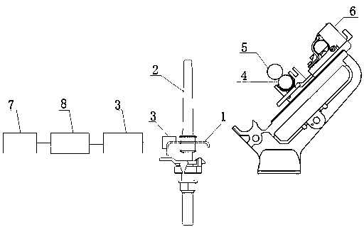

Image

  • Rough yarn feeding stopping automatic control system based on PLC

Examples


Embodiment Construction

[0013] It should be noted that the embodiments in the present application and the features in the embodiments can be combined with each other if there is no conflict. The present invention will be described in detail below with reference to the drawings and the embodiments.

[0014] In order to enable those skilled in the art to better understand the solution of the application, the technical solutions in the embodiments of the application will be clearly and completely described below in conjunction with the drawings in the embodiments of the application. Obviously, the described embodiments are only It is a part of the embodiments of this application, not all the embodiments. Based on the embodiments in this application, all other embodiments obtained by those of ordinary skill in the art without creative work should fall within the protection scope of this application.

[0015] Such as figure 1 As shown, a PLC-based automatic control system for roving stop feeding includes:

[0...


PUM


Abstract

The invention relates to a rough yarn feeding stopping automatic control system based on a PLC. The system includes a single-spindle detection control system, a rough yarn feeding stopping data acquisition control system, a rough yarn feeding stopping sub-control box, and a rough yarn feeding stopping shoveling mechanism. The single-spindle detection control system is used for detecting the operation state of a spindle. The rough yarn feeding stopping data acquisition control system is connected with a single-spindle detection control device, calculates data received from the single-spindle detection control system and transmits the data to the rough yarn feeding stopping sub-control box. The rough yarn feeding stopping sub-control box is connected with the rough yarn feeding stopping dataacquisition control system, and controls broken yarns or weak twisted spindles by receiving data transmitted by the rough yarn feeding stopping data acquisition control system. The rough yarn feedingstopping shoveling mechanism is arranged between a leather roller and a rear roller, and is connected with the rough yarn feeding stopping sub-control box. According to the system, the labor cost isreduced easily, the product quality is improved, broken ends and weak spindles are automatically monitored, in-time alarming and in-time rough yarn shoveling are achieved, the generation of weak twisted yarns and strong twisted yarns is effectively reduced, energy is saved, the efficiency is high, and the recycle rate of waste cotton is reduced.

Description

Technical field [0001] The invention belongs to the field of textile machinery, and particularly relates to a roving stop feeding control system of a ring spinning frame. Background technique [0002] With the improvement of the spinning electronic control system, the demand for the overall monitoring of the spinning frame is increasing. At present, there is no device on the market to monitor the single spindle of the spinning frame. The system cannot monitor the broken ends and weak spindles of the single spindle, and the staff needs to patrol the table many times to prevent the spindle from being abnormal and not being discovered in time. , Increase the workload of the staff, waste a lot of manpower, and cannot guarantee the quality of the yarn. In the face of the above technical problems, there has been no good solution. Summary of the invention [0003] In order to solve the above technical problems, the purpose of the present invention is to provide a roving stop feeding con...

Claims


Application Information

Patent Timeline
Patent Type & Authority Applications(China)
IPC IPC(8): D01H13/16
CPCD01H13/1616
Inventor 田雅萍杨为民叶景宋臣樊亚娟
Owner JINGWEI INTELLIGENT TEXTILE MACHINERY CO LTD
Learn More