
A rectangular molding device for cement pavement embossing

A cement pavement, rectangular technology, applied in the field of embossing molding devices, can solve the problems of poor control of embossing depth, easy to leave footprints, etc., and achieve the effect of convenient embossing, rapid embossing, and saving consumption

Active Publication Date: 2021-11-02
山东沂南园区开发建设有限公司
View PDF0 Cites 0 Cited by
  • Summary
  • Abstract
  • Description
  • Claims
  • Application Information

AI Technical Summary

Problems solved by technology

[0005] In order to overcome the shortcomings of the current method of embossing the cement pavement, the embossing depth is not easy to control, and it is easy to leave footprints. Therefore, the technical problem of the present invention is: to provide a cement pavement that can keep the embossing depth consistent and prevent residual footprints. Embossed rectangular molding device

Method used


Image

  • A rectangular molding device for cement pavement embossing
  • A rectangular molding device for cement pavement embossing
  • A rectangular molding device for cement pavement embossing

Examples


Embodiment 1

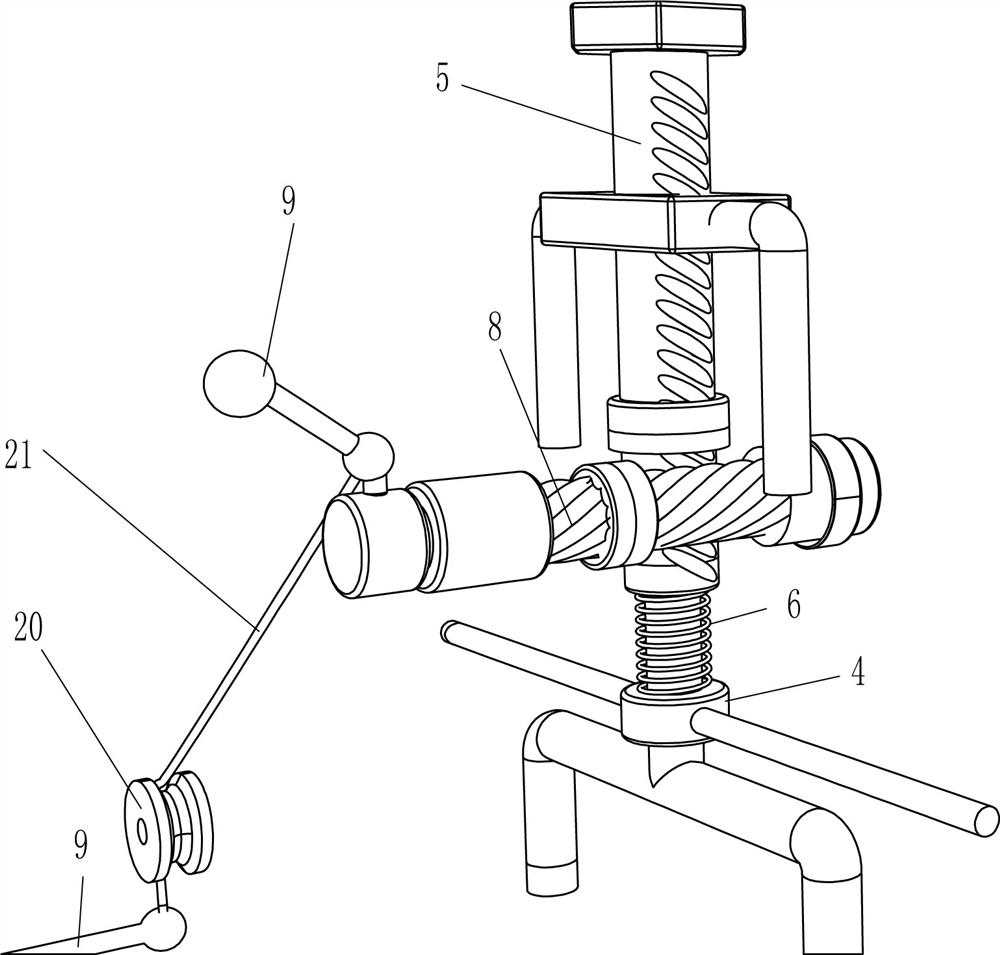
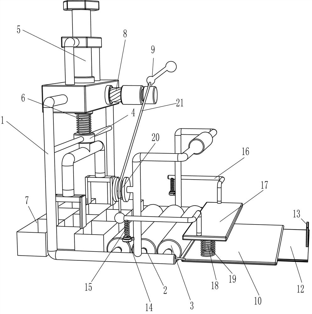
[0018] A cement pavement embossing rectangular molding device, such as figure 1 with 2 As shown, it includes a frame 1, a flattening assembly, an embossing assembly and a bottom plate 10. The middle part of the frame 1 is provided with a flattening assembly for flattening by rotation. The embossing assembly printed, the right part of the frame 1 is fixed with a bottom plate 10 by bolts.

[0019] Such as figure 1 As shown, the flattening assembly includes a connecting rod 2 and a rotating cylinder 3, three connecting rods 2 are rotatably arranged in the middle of the frame 1, and a rotating drum 3 is uniformly arranged on the connecting rod 2.

[0020] Such as figure 1 with 2 As shown, the embossing assembly includes a guide sleeve 4, a helical rack 5, a first spring 6, a printing template 7, a helical gear 8 and a handle 9, a guide sleeve 4 is welded in the middle of the left part of the frame 1, and the inside of the guide sleeve 4 The sliding type is equipped with a hel...

Embodiment 2

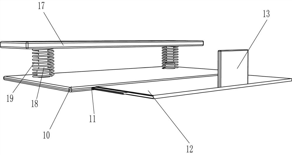
[0025] On the basis of Example 1, such as figure 1 with 3 Shown, also include mobile plate 12 and push plate 13, base plate 10 bottom right side has chute 11, sliding type is provided with mobile plate 12 in chute 11, and mobile plate 12 top right side is provided with push plate 13.

[0026] Such as figure 1 with 2 As shown, it also includes a connection block 14, a second spring 15, a special-shaped connecting rod 16, a pressing plate 17, a lifting and shrinking rod 18, a third spring 19, a fixed pulley 20 and a backguy 21, and the top of the bottom plate 10 is symmetrically provided with a lifting and shrinking rod. 18. There is a pressure plate 17 between the tops of the lifting and retracting rods 18, a third spring 19 is connected between the pressure plate 17 and the bottom plate 10, the top of the pressure plate 17 is symmetrically provided with special-shaped connecting rods 16, and the middle part of the frame 1 is symmetrically provided with connecting blocks 14....


PUM


Abstract

The invention relates to an embossing molding device, in particular to an embossing rectangular molding device for cement pavement. The technical problem to be solved by the present invention is how to provide a rectangular molding device for cement pavement embossing that can keep the embossing depth consistent and prevent residual footprints. A rectangular molding device for embossing cement pavement, which includes a frame; a flattening component installed on the frame, which is flattened by rotating; a stamping component, which is mounted on the frame, and is embossed by lifting; a bottom plate, Mounted on the rack. Through the cooperation of the connecting rod and the rotating cylinder, the invention can erase the footprints of the workers and prevent the footprints left on the cement road from affecting the appearance. Through the cooperation of the helical rack and the helical gear, the cement pavement can be imprinted quickly, while ensuring The depth of the imprint is consistent.

Description

technical field [0001] The invention relates to an embossing molding device, in particular to an embossing rectangular molding device for cement pavement. Background technique [0002] Cement pavement, among roads, urban roads and airport pavements, the most widely used in our country is the ordinary concrete pavement poured on site. After some cement pavements are paved, in order to increase the beauty of the cement pavement, it is necessary to emboss the pavement. , the rectangular shape is the most common one. [0003] At present, when embossing a rectangular shape on the cement pavement, a person needs to hold the molding mold, then step on the cement road surface, then place the molding mold on the top of the cement road surface, and then press it down firmly, leaving a rectangular shape on the cement road surface. Imprint, although this method can imprint a rectangular imprint, but the depth of the imprint is not easy to control, and it is easy to leave footprints on ...

Claims


Application Information

Patent Timeline
Patent Type & Authority Patents(China)
IPC IPC(8): E01C19/43
CPCE01C19/43
Inventor 张秀金
Owner 山东沂南园区开发建设有限公司
Learn More