Street lamp with solar power generation function
A solar energy and solar panel technology, applied in the field of street lamps with solar power generation functions, can solve the problems of single structure of street lamps, affecting the expansion of street lamp functionality, inconvenient lighting effects of solar panel lighting, etc., to achieve better functionality
- Summary
- Abstract
- Description
- Claims
- Application Information
AI Technical Summary
Problems solved by technology
Method used
Image

Examples
Embodiment 1
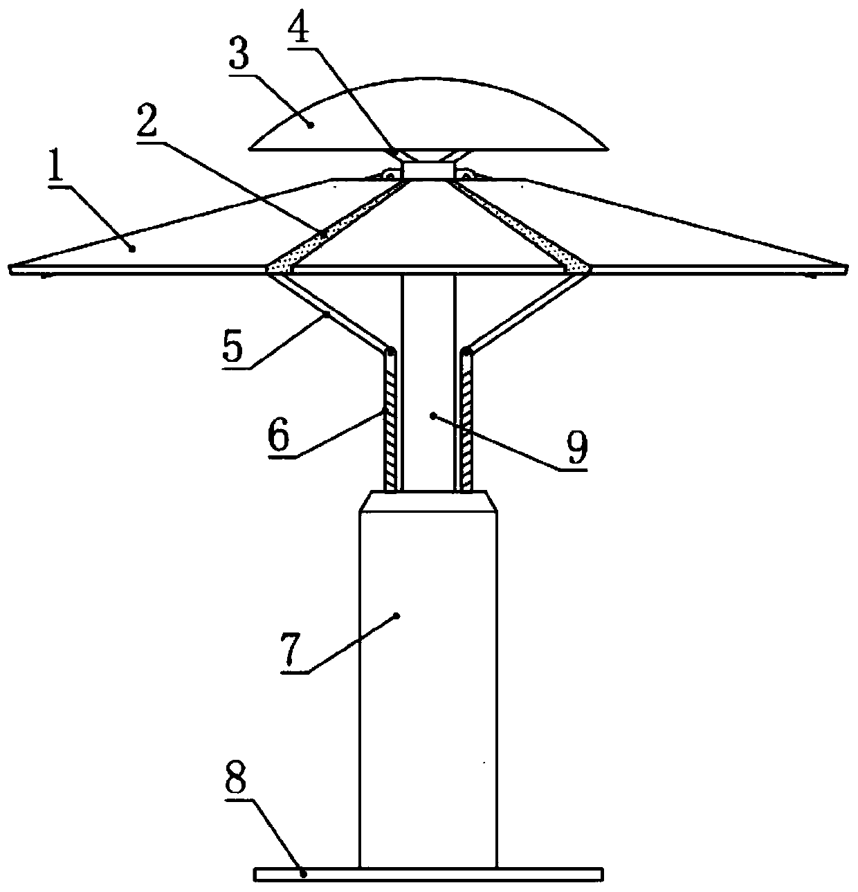
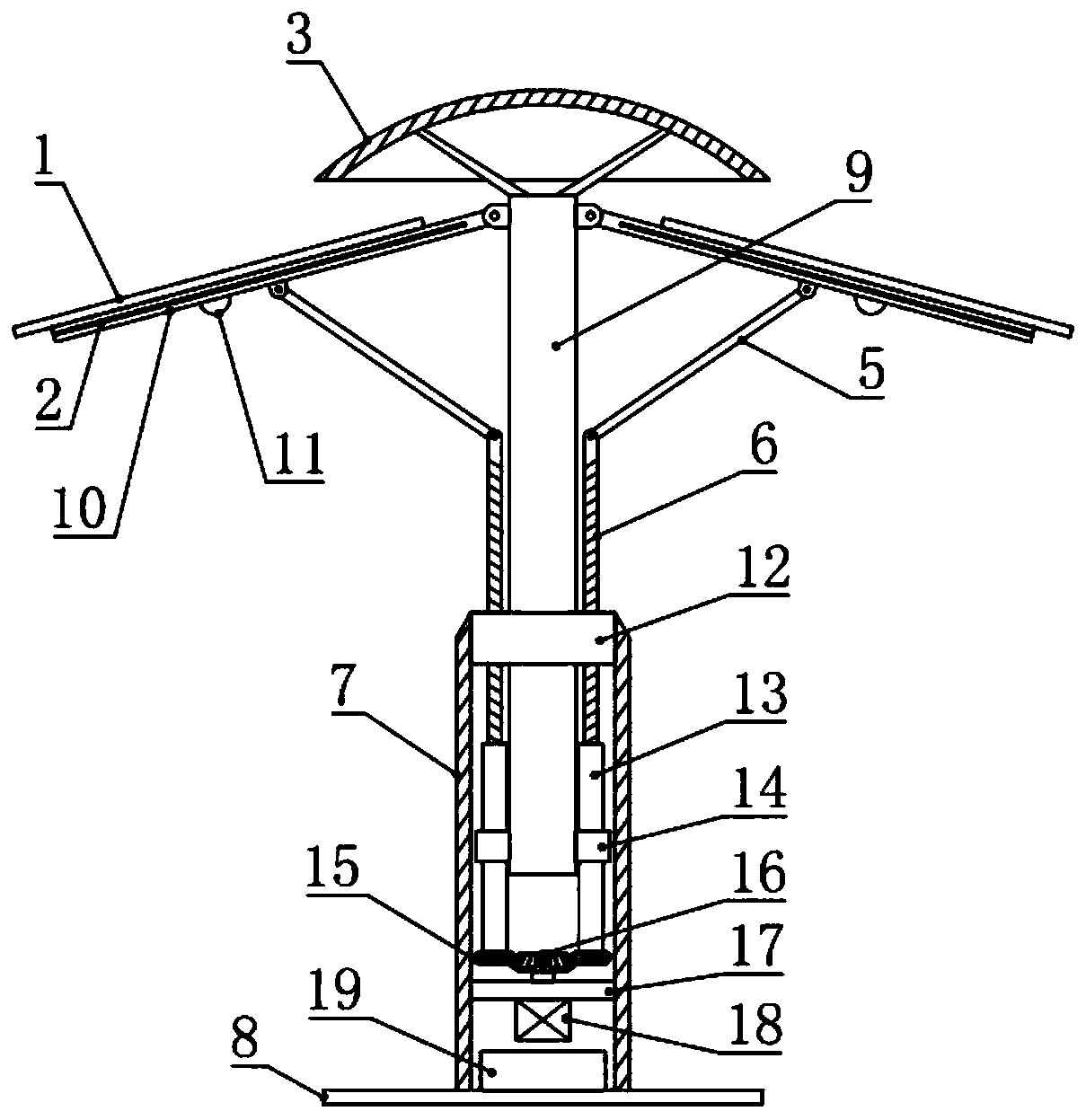
[0017] see Figure 1-2 , in an embodiment of the present invention, a street lamp with solar power generation function includes a mounting base 8, a vertical tube 7 is mounted and fixed on the mounting base 8, a fixed plate 12 is mounted and fixed on the inner side of the upper end of the vertical tube 7, and the fixed plate 12 is fixed A column 9 is installed and fixed in the middle of the disc 12, and a rain cover 3 is installed and fixed on the upper end of the column 9. The upper end of the column 9 is also circumferentially distributed and hinged to be provided with a plurality of installation rods 10, and the upper side of the installation rod 10 is installed and fixed with solar energy. Panel 1, elastic rain cloth 2 is connected between two adjacent solar panels 1, lighting lamps 11 are installed on the underside of the installation rod 10, and the lower side of the installation rod 10 is also hingedly provided with a connecting rod 5, and the connecting rod The other e...
Embodiment 2
[0020] see Figure 1-4 , the difference between this embodiment and embodiment 1 is:
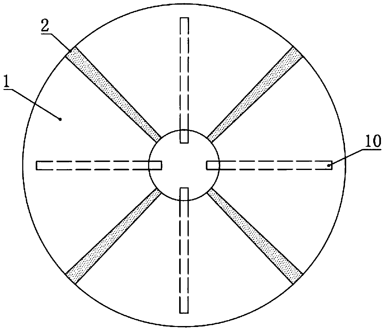
[0021] In this example, if Figure 1-3 As shown, three installation rods 10 are evenly distributed in the circumferential direction, and the lower middle part of the solar panel 1 is connected and fixed with the installation rods 10, and the top view projection of the solar panel 1 is fan-shaped, and the solar panel 1 is arc-shaped in the middle. structure; the hole surrounded by the top view projection of the solar panel 1 and the elastic rainproof cloth 2 is circular; And the top view projection diameter of the rain cover 3 is larger than the hole diameter surrounded by the top view projection of the solar panel 1 and the elastic rain cloth 2, and the rain cover 3 has a better shielding effect on the hole. The lower side is also circumferentially distributed and fixed with multiple diagonal struts 4, and the lower end of the diagonal struts 4 is fixed on the upper end of the column 9, an...
PUM
 Abstract
Description
Claims
Application Information
 - R&D
- Intellectual Property
- Life Sciences
- Materials
- Tech Scout
- Unparalleled Data Quality
- Higher Quality Content
- 60% Fewer Hallucinations
Browse by: Latest US Patents, China's latest patents, Technical Efficacy Thesaurus, Application Domain, Technology Topic, Popular Technical Reports.
© 2025 PatSnap. All rights reserved.Legal|Privacy policy|Modern Slavery Act Transparency Statement|Sitemap|About US| Contact US: help@patsnap.com