Scratch-resistant brightness enhancement film
A brightening film, anti-scratch technology, applied in optics, instruments, optical components, etc., can solve the problems of high cost of elastic materials, loss of optical properties, poor optical effects, etc., to improve wear resistance, take into account optical functions, avoid The effect of adsorption
- Summary
- Abstract
- Description
- Claims
- Application Information
AI Technical Summary
Problems solved by technology
Method used
Image
Examples
Embodiment 1
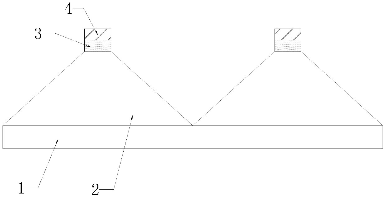
[0023] Such as figure 1 As shown, in order to achieve the purpose of the present invention, this embodiment provides a scratch-resistant brightness enhancement film, including a substrate 1, the outer surface of the upper end of the substrate 1 is provided with a prism layer 2, and the outer surface of the upper end of the prism layer 2 is A reflective layer 3 is provided on the surface, and a rough layer 4 is provided on the outer surface of the upper end of the reflective layer 3 .
[0024] Further, the substrate 1 is a transparent substrate, and the thickness of the substrate 1 is 15-300 μm.
[0025] Further, the material of the prism layer 2 is photocurable acrylic resin, and the optical function lost by the tip of the prism is compensated by the flat-top reflective structure.
[0026] Further, the roughness layer 4 can be embossed with photocurable resin or coated with a layer of diffusion particles, with a roughness range of Ra: 0.5-25 μm, which can avoid the adsorption...
Embodiment 2
[0028] Such as figure 2 As shown, in order to further optimize the implementation effect of the present invention, the rest are the same as in Example 1, except that two fixing blocks 5 are respectively arranged on the upper and lower sides of the anti-scratch and brightness-enhancing film. Positioning holes are arranged on the fixing block 5 . This embodiment facilitates the fixing and positioning of the anti-scratch brightness enhancing film through the fixing block and the positioning hole.
Embodiment 3
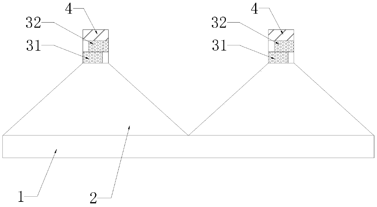
[0030] Such as image 3 As shown, in order to further optimize the implementation effect of the present invention, the rest are the same as in Embodiment 1, except that the reflective layer 3 includes a lower reflective layer 31 and an upper reflective layer 32, and the lower reflective layer 31 includes a lower reflective layer Layer body and filling layer, the upper reflection layer 32 includes the upper reflection layer body and the filling layer, the lower reflection layer 31, the upper reflection layer 32 are arranged on the upper end outer surface of the prism layer 2 from bottom to top in turn, and the lower reflection layer The body and the body of the upper reflection layer are alternately arranged. Wherein, the material of the lower reflective layer body and the upper reflective layer body is a metal layer, a silver-plated layer, an aluminum-plated layer or a TiO coating. 2 Filler white coating. In this embodiment, the upper and lower reflective layer bodies are ar...
PUM
| Property | Measurement | Unit |
|---|---|---|
| thickness | aaaaa | aaaaa |
| surface roughness | aaaaa | aaaaa |
Abstract
Description
Claims
Application Information
 - R&D
- Intellectual Property
- Life Sciences
- Materials
- Tech Scout
- Unparalleled Data Quality
- Higher Quality Content
- 60% Fewer Hallucinations
Browse by: Latest US Patents, China's latest patents, Technical Efficacy Thesaurus, Application Domain, Technology Topic, Popular Technical Reports.
© 2025 PatSnap. All rights reserved.Legal|Privacy policy|Modern Slavery Act Transparency Statement|Sitemap|About US| Contact US: help@patsnap.com


