Local smooth trajectory planning method based on curved column coordinate system

A cylindrical coordinate system and trajectory planning technology, which is applied in control/regulation systems, two-dimensional position/channel control, non-electric variable control, etc., can solve problems such as poor trajectory continuity and smoothness, and difficult trajectory constraints

Active Publication Date: 2020-08-18
宁波智能装备研究院有限公司
View PDF9 Cites 6 Cited by
  • Summary
  • Abstract
  • Description
  • Claims
  • Application Information

AI Technical Summary

Problems solved by technology

[0006] The present invention aims to solve the problem of poor trajectory continuity and smoothness and difficult trajectory constraints in the existing local path planning methods for unmanned vehicles in three-dimensional space, and proposes a local smooth trajectory planning method based on a curved cylindrical coordinate system

Method used


Image

  • Local smooth trajectory planning method based on curved column coordinate system
  • Local smooth trajectory planning method based on curved column coordinate system
  • Local smooth trajectory planning method based on curved column coordinate system

Examples


specific Embodiment approach 1

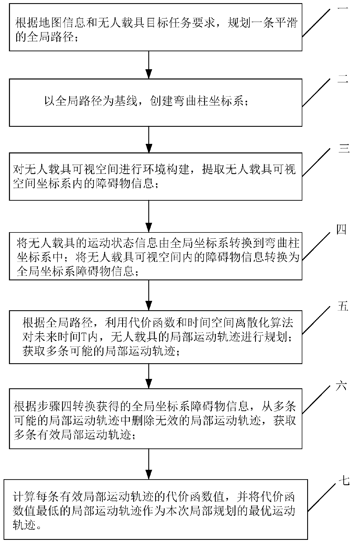
[0055] Specific implementation mode 1. Combination Figure 1 to Figure 3 Describe this embodiment, a local smooth trajectory planning method based on a curved cylindrical coordinate system described in this embodiment, the specific steps of the method are:

[0056] Step 1: Plan a smooth global path according to the map information and the target mission requirements of the unmanned vehicle;

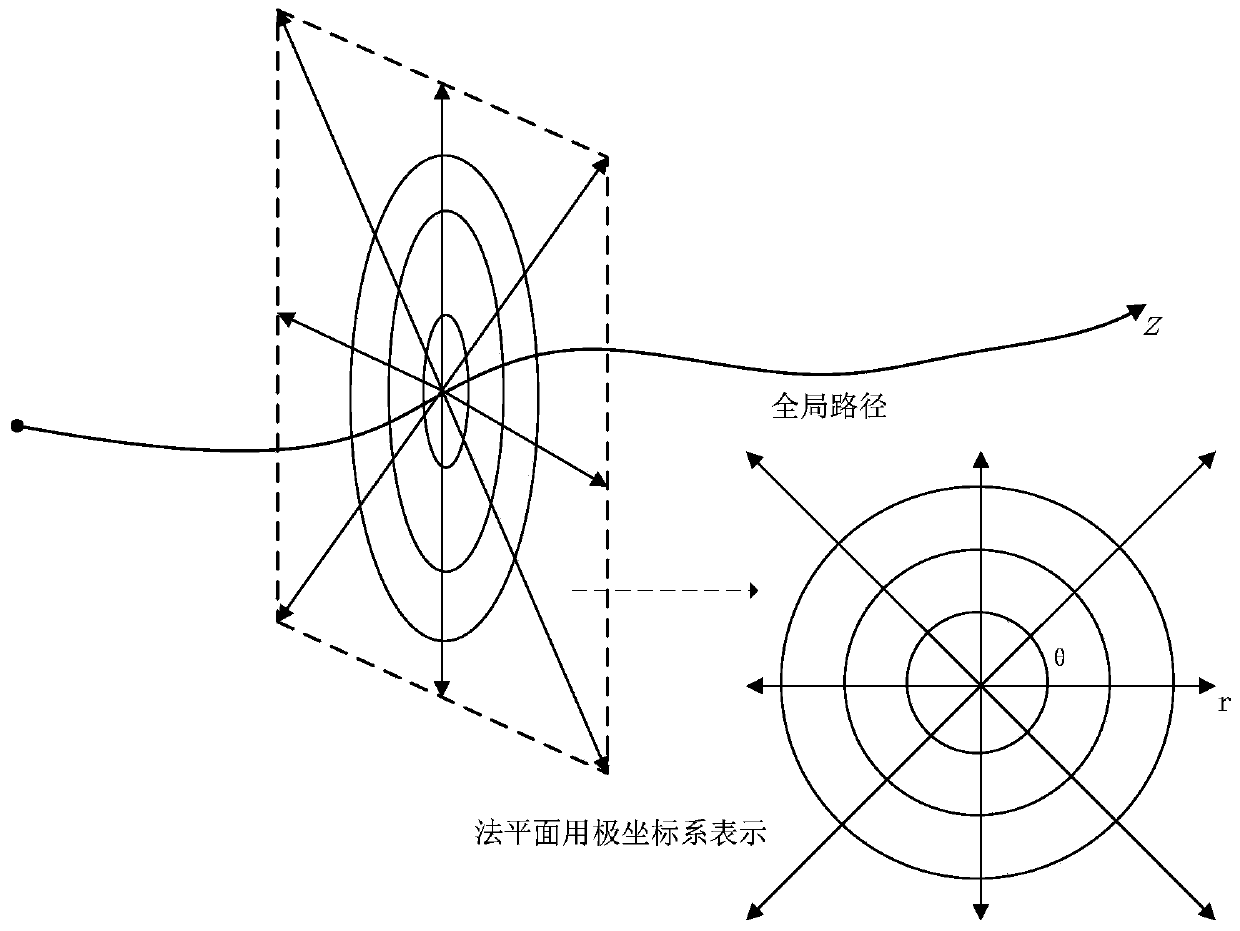
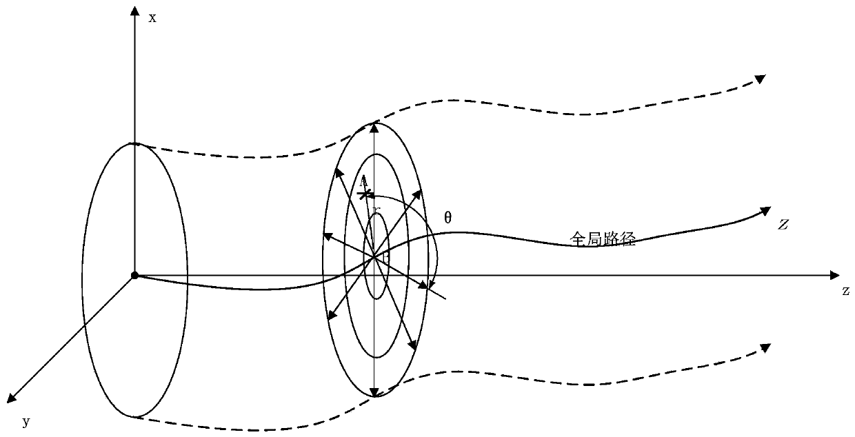
[0057] Step 2: Create a curved cylindrical coordinate system with the global path as the baseline;

[0058] Step 3: Construct the environment of the visible space of the unmanned vehicle, and extract the obstacle information in the coordinate system of the visible space of the unmanned vehicle;

[0059] Step 4: Convert the motion state information of the unmanned vehicle from the global coordinate system to the curved cylindrical coordinate system; convert the obstacle information in the visible space of the unmanned vehicle into the obstacle information of the global coordinate system; ...

specific Embodiment

[0109] combine Figure 4 to Figure 7 This embodiment is described, which describes a local trajectory planning method for an unmanned vehicle based on a curved cylindrical coordinate system.

[0110]Specifically: in a long corridor with an average width and height of 3m, let the drone fly at a constant speed of 5m / s. Occasionally, pedestrians will pass by in the corridor, and doors will open occasionally (various unmodeled obstacles). Suppose the unmanned vehicle is a quadrotor aircraft with a wheelbase of 200, the upper limit of speed is 10m / s, and the upper limit of acceleration is 5m / s 2 , the curvature is not constrained, and the positioning system relies on UWB positioning. Assume that the initial position of the quadrotor is at the global coordinate (1,0,0), and the initial velocity and initial acceleration are both 0.

[0111] Step 1: Plan a smooth global path according to the map information. In this example, it can be set as a global path along the centerline of the...


PUM


Abstract

The invention discloses a local smooth trajectory planning method based on a bent cylindrical coordinate system, and belongs to the technical field of unmanned carrier trajectory planning. According to the method, the problems of poor track continuity and smoothness and difficult track constraint of an existing unmanned vehicle local path planning method in a three-dimensional space are solved. According to the method, a smooth global path is planned according to map information and unmanned carrier target task requirements; taking the global path as a base line, and creating a bent column coordinate system; converting the motion state information of the unmanned vehicle from a global coordinate system to a bent column coordinate system; according to the global path, planning a local motion trail of the unmanned vehicle in future time T by utilizing a cost function and time space discretization; deleting the local motion trails which collide with the obstacle and exceed the power constraint range of the unmanned vehicle, and taking the local motion trail with the lowest cost function value as the optimal motion trail of local planning. The method is suitable for planning the localmotion trail of the unmanned vehicle.

Description

technical field [0001] The invention belongs to the technical field of trajectory planning of unmanned vehicles. Background technique [0002] In recent years, unmanned vehicles in three-dimensional space, such as small unmanned submarines and unmanned aerial vehicles, have attracted a large number of domestic and foreign researchers due to their simple models, convenient production, quick response, good maneuverability, and low cost. s concern. However, in the complex three-dimensional space, real-time planning of a local path that can successfully avoid obstacles, have a smooth trajectory, and do not change the state of motion has always been one of the main research topics to achieve high-dynamic operation of unmanned vehicles. It is still a very challenging task to ensure that in the three-dimensional space, it is necessary to quickly and smoothly pass through a long straight area with unknown obstacles in advance, and to successfully and accurately avoid obstacles to r...

Claims


Application Information

Patent Timeline
Patent Type & Authority Applications(China)
IPC IPC(8): G05D1/02
CPCG05D1/0214G05D1/0221G05D1/0223G05D1/0251G05D1/0276G05D1/0217
Inventor 高会军李湛宋罘林于兴虎
Owner 宁波智能装备研究院有限公司
Why Eureka
Try Eureka