Firefighting pipe paint spraying device

A technology for fire-fighting pipes and fixtures, applied in spraying devices, cleaning methods and utensils, chemical instruments and methods, etc., can solve problems such as low efficiency, human health injury, unacceptable production scale factories, etc. Effect

Active Publication Date: 2020-08-21
万嘉颖
View PDF6 Cites 7 Cited by
  • Summary
  • Abstract
  • Description
  • Claims
  • Application Information

AI Technical Summary

Problems solved by technology

[0006] The present invention overcomes the disadvantages of painting with a spray gun or a brush in hand. Not only is the efficiency low, but also the long-term contact with the paint will cause harm to human health. However, the current automatic paint spraying machine is expensive and the factory with an average production scale Unacceptable shortcomings, the technical problem to be solved by the present invention is to provide a fire-fighting pipeline paint spraying device with low production cost, simple operation, automatic surface cleaning, automatic paint spraying, and uniform paint spraying

Method used


Image

  • Firefighting pipe paint spraying device
  • Firefighting pipe paint spraying device
  • Firefighting pipe paint spraying device

Examples


Embodiment 1

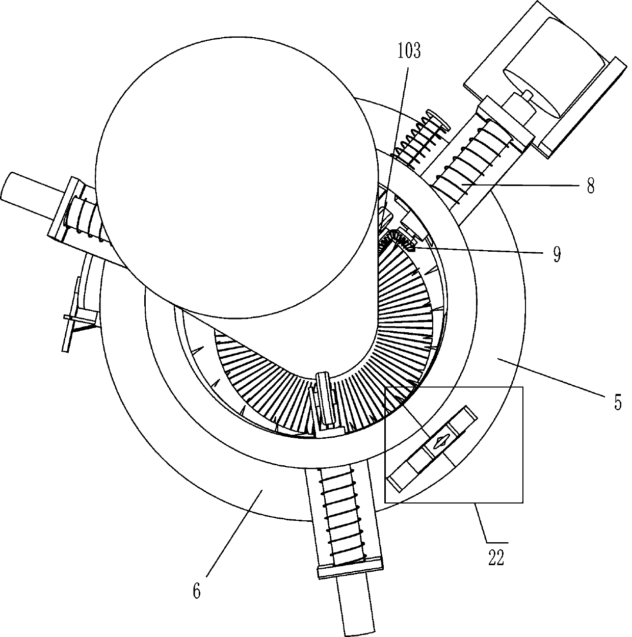
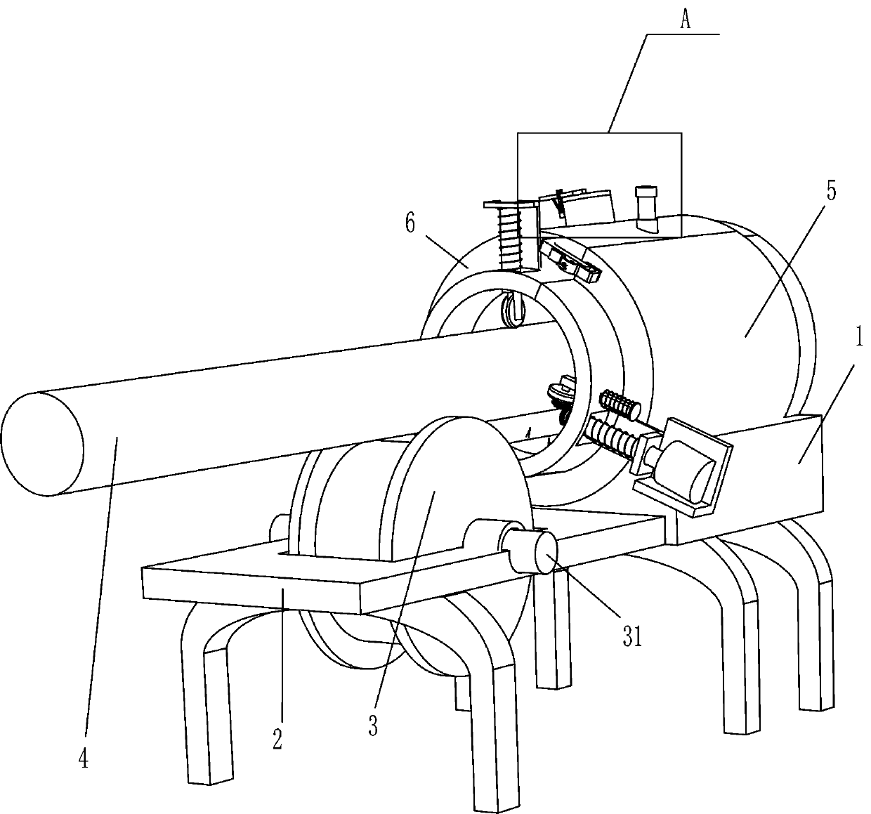
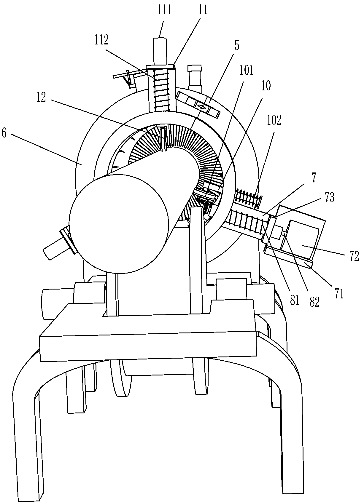
[0060] A fire pipe painting device, such as Figure 1-2As shown, include support 1, push frame 2, sliding wheel 3, rolling shaft 31, shell assembly one 5, shell assembly two 6, support frame one 7, support frame two 71, motor 72, support frame three 73, Guide rod 8, compression spring 81, rotating shaft 82, bevel gear 9, wheel support rod 10, transmission wheel 101, coil spring 102, transmission connecting shaft 103, supporting device, feeding device and fixing device 22, push frame 2 are fixed on On the front side above the bracket 1, the rolling shaft 31 is rotatably connected between the left and right side walls in the push frame 2, the sliding wheel 3 is fixedly connected to the rolling shaft 31, and the shell assembly one 5 and the shell assembly two 6 are two semicircular structures , and form a circle after being combined, the shell assembly one 5 and the shell assembly two 6 are movably arranged at the upper rear part of the bracket 1, the support frame one 7 is fixed...

Embodiment 2

[0063] On the basis of Example 1, such as Figure 1-6 As shown, the support device includes a support plate 11, a slide bar 111, a telescopic spring 112 and auxiliary wheels 12, and the two support plates 11 are affixed to the upper and lower sides of the outer shell assembly two 6, and the outer sides of the two support plates 11 are Vertically slidingly connected with a slide bar 111, the inner end of the slide bar 111 slides through the shell assembly 26, the telescopic spring 112 is wound on the slide bar 111, one end of the telescopic spring 112 is connected to the support plate 11, and the other end is connected to the slide bar 111 , the inner end of the slide bar 111 is equipped with auxiliary wheels 12 .

[0064] When the fire-fighting pipeline 4 is in contact with the auxiliary wheels 12, the fire-fighting pipeline 4 pushes the auxiliary wheels 12 to drive the slide bar 111 to move outward. At the same time, the telescopic spring 112 is compressed. The auxiliary whe...


PUM


Abstract

The invention relates to paint spraying devices, in particular to a firefighting pipe paint spraying device which is provided for achieving the technical effects of being low in manufacturing cost, easy to operate, capable of automatically cleaning a surface layer and automatically spraying paint and uniform in paint spraying. In order to achieve the technical effects, the firefighting pipe paintspraying device provided by the invention comprises a support, a push frame fixed to the support, a rolling shaft rotatably connected with the push frame, a sliding wheel fixedly connected to the rolling shaft and an outer shell combined part I movably arranged on the side, close to the sliding wheel, of the push frame. According to the firefighting pipe paint spraying device, a firefighting pipecan be protected against deviation in a pipeline through a supporting device, and the surface layer of the firefighting pipe can be cleaned through a brush so that paint can be sprayed on the smooth surface of the firefighting pipe. A plurality of paint spray nozzles are arranged in a circular mode.

Description

technical field [0001] The invention relates to a paint spraying device, in particular to a fire-fighting pipeline paint spraying device. Background technique [0002] The fire pipe connection method is threaded, grooved, flanged, etc. The fire-fighting pipeline is to transport fire-fighting water, lead the water in the fire-fighting water tank or pool to the fire hydrant in the building, and lead the water in the fire-fighting water tank or pool to the automatic sprinkler pipe in the building. In the spout of the automatic sprinkler system, a glass ball tops the water spout and bursts under high temperature. The water in the pipe is under pressure and is sprayed out from the spout. As the name suggests, the fire-fighting pipeline is a pipeline system established for fire-fighting. Due to special needs, the thickness and material of the fire-fighting pipeline have special requirements, and it is sprayed with red paint to transport fire-fighting water. Fire-fighting pipelin...

Claims


Application Information

Patent Timeline
Patent Type & Authority Applications(China)
IPC IPC(8): B05B13/02B08B1/02
CPCB05B13/0214B05B13/0278B08B1/002B08B1/02
Inventor 万嘉颖
Owner 万嘉颖
Why Eureka
Try Eureka