
Corrugation depth detection equipment for a core diaphragm

A technology of depth detection and diaphragm, which is applied in the direction of measuring devices, mechanical measuring devices, instruments, etc., can solve the problems of inconvenient preparation, manual fine-tuning, and the complexity of increase and decrease detection operations, so as to avoid manual adjustment and reduce preparation work volume effect

Active Publication Date: 2020-09-29
NANJING WOTIAN TECH
View PDF6 Cites 0 Cited by
  • Summary
  • Abstract
  • Description
  • Claims
  • Application Information

AI Technical Summary

Problems solved by technology

[0002] After the core is produced, it is necessary to detect the corrugation depth of its diaphragm to ensure its normal structure and normal body function. The existing detection technology is usually a laser displacement sensor to test the core diaphragm (on the sensor) surface sealing film) under pressurized and normal conditions, the peak and trough depth dimensions of the surface corrugation of the core diaphragm are used to check whether the corrugation state of the diaphragm surface meets certain requirements. However, due to the small size of the chip, After the detection platform, manual fine-tuning is required to ensure the normal detection of the sensor, which brings a lot of inconvenience to the preparation work before detection, and increases or decreases the complexity of the detection operation. Therefore, a corrugation depth detection equipment for the core diaphragm is proposed.

Method used


Image

  • Corrugation depth detection equipment for a core diaphragm
  • Corrugation depth detection equipment for a core diaphragm
  • Corrugation depth detection equipment for a core diaphragm

Examples


Embodiment Construction

[0016] The following will clearly and completely describe the technical solutions in the embodiments of the present invention with reference to the accompanying drawings in the embodiments of the present invention. Obviously, the described embodiments are only some, not all, embodiments of the present invention. Based on the embodiments of the present invention, all other embodiments obtained by persons of ordinary skill in the art without making creative efforts belong to the protection scope of the present invention.

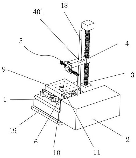
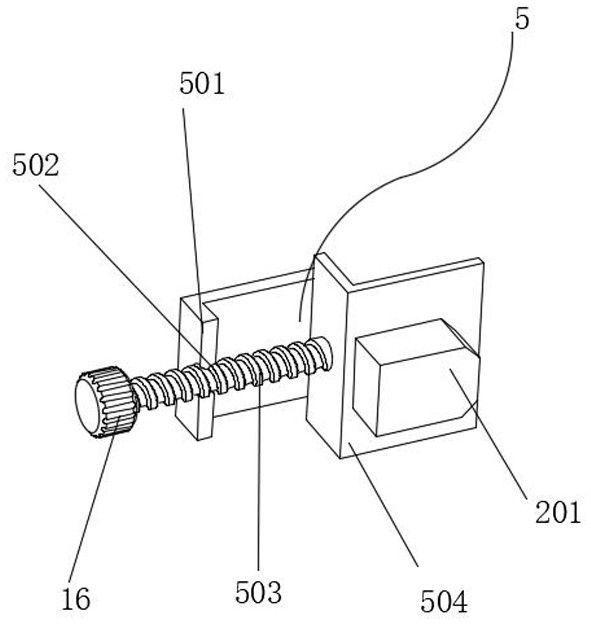
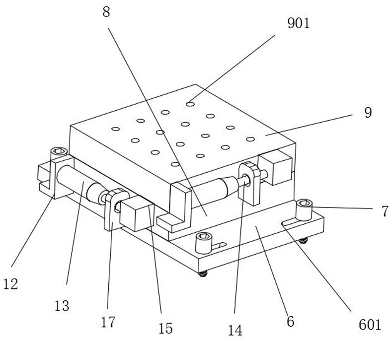
[0017] see Figure 1-3 , the present invention provides a technical solution: a corrugation depth detection device for a core diaphragm, including a base 1, a data recorder 2 is fixedly installed on the right side wall of the base 1, and the data recorder 2 is electrically connected to a laser displacement sensor 201, The rear end of the upper surface of the base 1 is fixed with a screw lifter 3, the front side wall of the screw lifter 3 is fixed with a transm...


PUM


Abstract

The invention relates to the technical field of detection equipment, and discloses a corrugation depth detection equipment for a core diaphragm. A data recorder is fixedly installed on the right side wall of the base. The data recorder is electrically connected to a laser displacement sensor, and the rear end of the upper surface of the base is fixedly installed. Screw lift, the front side wall of the moving end of the screw lift is fixedly installed with a transmission rod, the front side wall of the transmission rod is fixedly installed with a fixing device, the front side wall of the fixing device is fixedly connected to the rear side wall of the laser displacement sensor, and the upper surface of the base is fixedly installed with an assembly plate, assembled The upper surface of the plate is provided with assembly holes, the inner wall of the assembly hole is plugged with bolts, the upper surface of the assembly plate is attached to the first adjustment plate, the upper surface of the first adjustment plate is attached to the second adjustment plate, and the upper surface of the second adjustment plate is provided with positioning holes, which realizes The adjustment of the equipment by the screw lifter and the transmission cylinder avoids manual adjustment and reduces the preparation workload before the experiment.

Description

technical field [0001] The invention relates to the technical field of detection equipment, in particular to a corrugation depth detection equipment of a core diaphragm. Background technique [0002] After the core is produced, it is necessary to detect the corrugation depth of its diaphragm to ensure its normal structure and normal body function. The existing detection technology is usually a laser displacement sensor to test the core diaphragm (on the sensor) Surface sealing film) Under the condition of pressurization and normal state, the peak and trough depth dimensions of the surface corrugation of the core diaphragm are used to test whether the corrugation state of the diaphragm surface meets certain requirements. However, due to the small size of the chip, the fixed After the detection platform, manual fine-tuning is required to ensure the normal detection of the sensor, which brings a lot of inconvenience to the preparation work before the detection and increases or ...

Claims


Application Information

Patent Timeline
Patent Type & Authority Patents(China)
IPC IPC(8): G01B11/22G01B11/02G01B5/00
CPCG01B5/0004G01B11/02G01B11/22
Inventor 王旭翟红星
Owner NANJING WOTIAN TECH
Learn More