Capacitance-controlled electromagnetic computer mainboard fixing device

A computer motherboard, capacitor control technology, applied in computing, electrical digital data processing, digital processing power distribution, etc., can solve problems such as easy loosening of the motherboard, damage to host materials, and difficulty in saving screws, so as to avoid unstable fixing and ensure normal operation. Use, improve the effect of fixed effects

Active Publication Date: 2020-08-21
ELECTRIC POWER RES INST OF GUANGXI POWER GRID CO LTD +1
View PDF10 Cites 3 Cited by
  • Summary
  • Abstract
  • Description
  • Claims
  • Application Information

AI Technical Summary

Problems solved by technology

[0003] Most of the current computer mainboards are fixed on the inner wall of the computer mainframe by screws, which requires drilling holes on the inner surface of the mainframe shell first, which may cause damage to the mainframe material and affect the service life of the mainframe shell, and when the mainframe is in use, Vibration will occur, and long-term vibration will cause the screws to loosen, causing the risk of the main board falling off, and the parts of the main board are relatively precise, and the impact after falling off may cause damage to the main board and affect the use, and the screws are difficult to save during the disassembly process. The screws are often lost, resulting in the motherboard not being firmly fixed, making the motherboard more likely to loosen

Method used


Image

  • Capacitance-controlled electromagnetic computer mainboard fixing device
  • Capacitance-controlled electromagnetic computer mainboard fixing device
  • Capacitance-controlled electromagnetic computer mainboard fixing device

Examples


Embodiment Construction

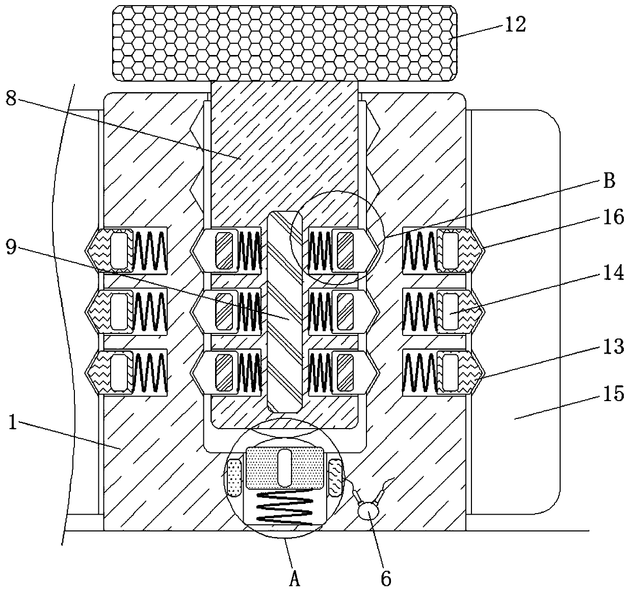
[0020] The following will clearly and completely describe the technical solutions in the embodiments of the present invention with reference to the accompanying drawings in the embodiments of the present invention. Obviously, the described embodiments are only some, not all, embodiments of the present invention. Based on the embodiments of the present invention, all other embodiments obtained by persons of ordinary skill in the art without making creative efforts belong to the protection scope of the present invention.

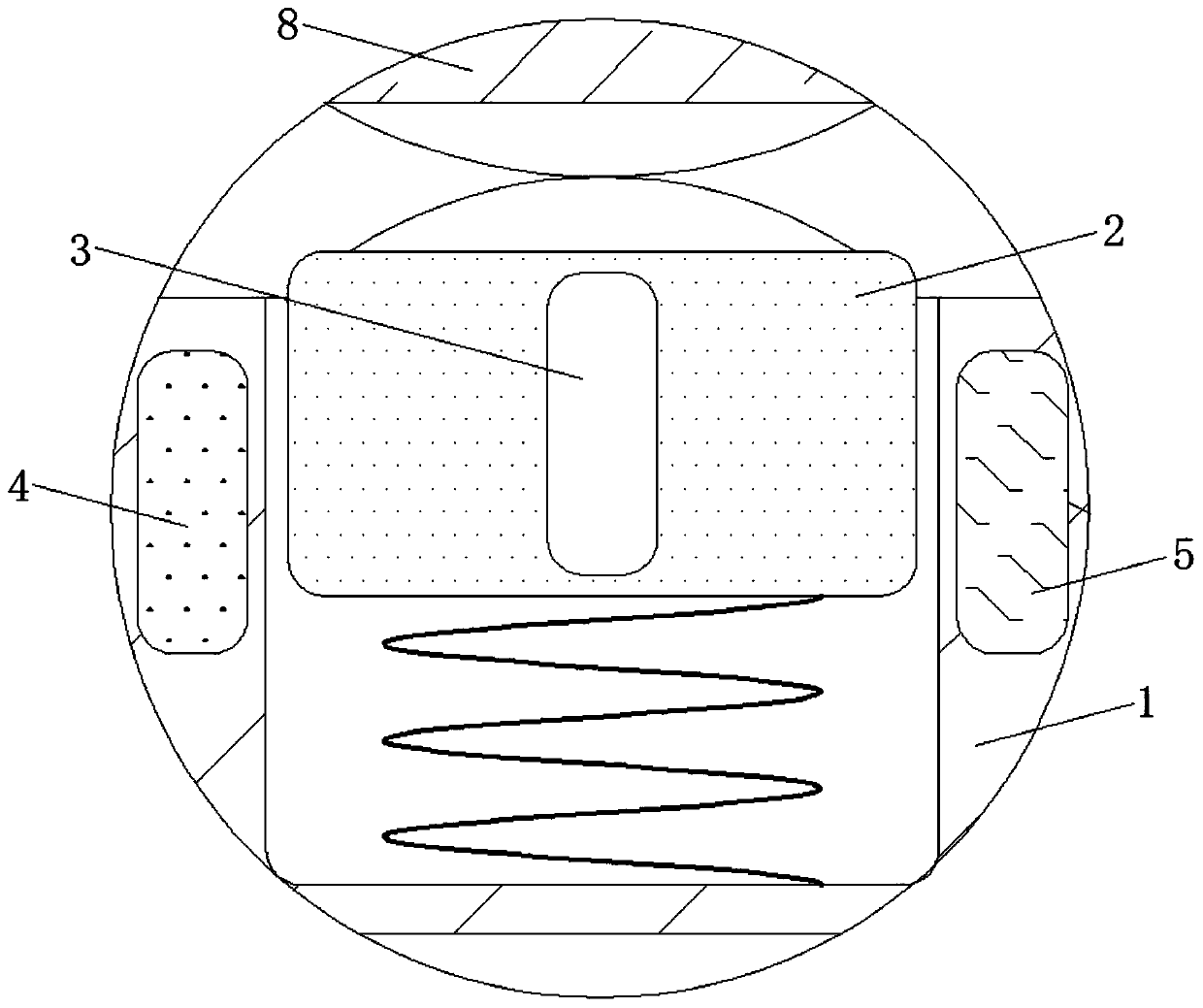
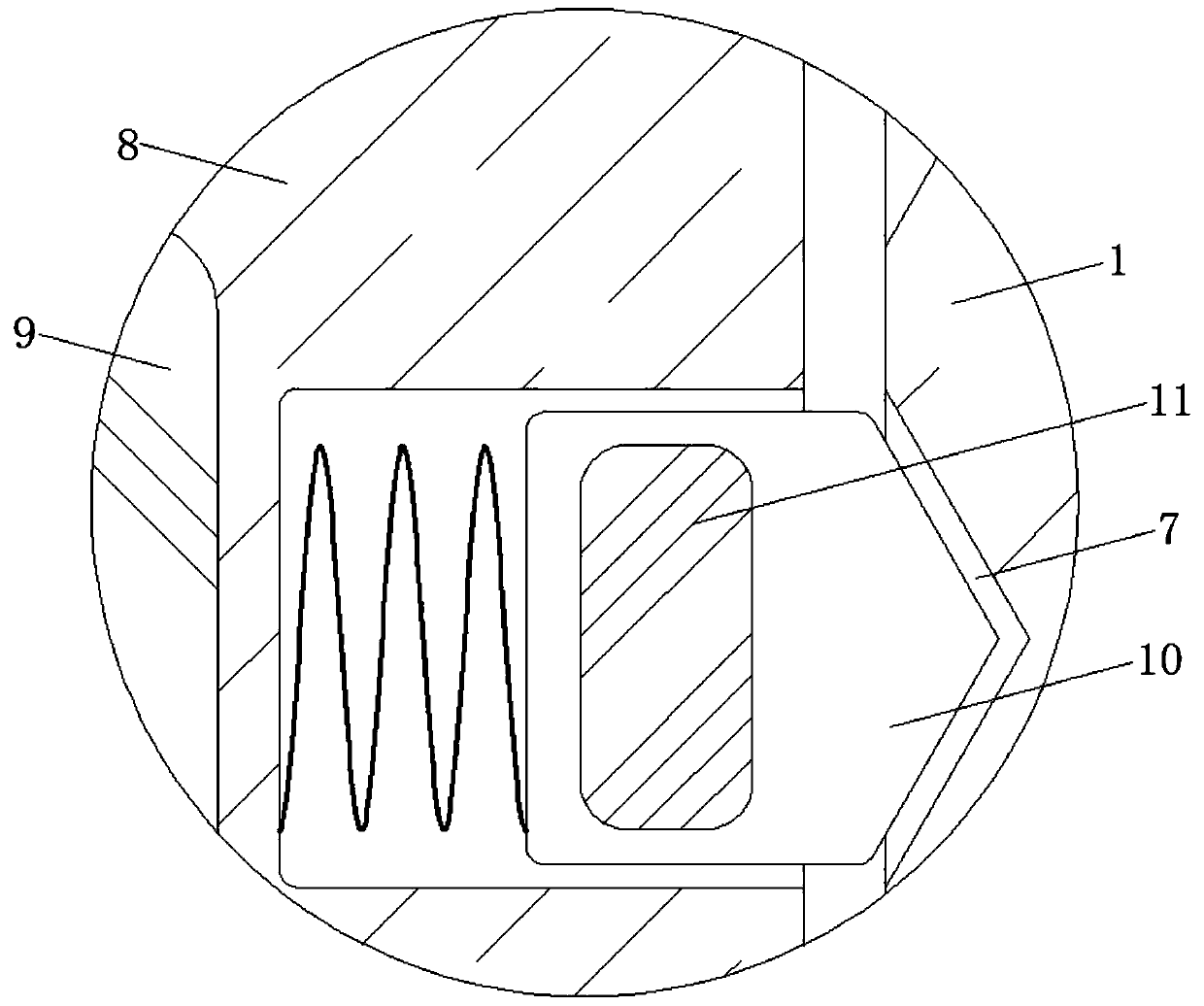
[0021] see Figure 1-5 , a capacitance-controlled electromagnetic computer motherboard fixing device, comprising a fixed post 1, the fixed post 1 plays the role of fixing each component, the material of the fixed post 1 is a hard high-strength material and the shape of the fixed post 1 is cylindrical, The material of the conductive block 2 is copper material and the shape of the conductive block 2 is a cuboid. The size of the dielectric plate 3 is smaller than...


PUM


Abstract

The invention discloses a capacitance-controlled electromagnetic computer mainboard fixing device, and relates to the technical field of computer mainboards. The capacitance-controlled electromagneticcomputer mainboard fixing device includes a fixing column, the inner bottom wall of the fixing column is movably connected with a conductive block; a dielectric plate is fixedly connected to the middle of the conductive block, a positive plate is fixedly connected to the inner wall of the bottom of the fixing column and close to the left side of the conductive block, a negative plate is fixedly connected to the inner wall of the bottom of the fixing column and close to the right side of the conductive block, and a resistor electrically connected with the negative plate is fixedly connected tothe inner wall of the bottom of the fixing column. According to the capacitance-controlled electromagnetic computer mainboard fixing device, an electromagnet is matched with a magnetic block II for use; when a host is used, at the moment, a circuit of the electromagnet is also in a power-on state, and the outer side of the electromagnet generates the same magnetism as the inner side of the secondmagnetic block, so that the second magnetic block can move outwards under the magnetic repulsion effect of the electromagnet, clamping of the positioning block and the positioning groove is enhanced,loosening of the mainboard is effectively prevented, the stability of the mainboard is improved, and normal use of the mainboard is guaranteed.

Description

technical field [0001] The invention relates to the technical field of computer motherboards, in particular to an electromagnetic computer motherboard fixing device controlled by capacitance. Background technique [0002] Computer motherboard is also called motherboard, system board or motherboard; it is divided into two types: commercial motherboard and industrial motherboard. It is installed in the case and is one of the most basic and important components of a microcomputer. The motherboard is generally a rectangular circuit board. The main circuit system that makes up the computer is installed on it, generally including BIOS chips, I / O control chips, keyboard and panel control switch interfaces, indicator light connectors, expansion slots, motherboards and DC power supply connectors for cards, etc. . [0003] Most of the current computer mainboards are fixed on the inner wall of the computer mainframe by screws, which requires drilling holes on the inner surface of the ...

Claims


Application Information

Patent Timeline
Patent Type & Authority Applications(China)
IPC IPC(8): G06F1/18
CPCG06F1/184
Inventor 龚泳畅
Owner ELECTRIC POWER RES INST OF GUANGXI POWER GRID CO LTD
Why Eureka
Try Eureka