
Beam switching method and device

A technology of beam switching and beam, which is applied in the field of communication, can solve problems such as frequent switching of beams, achieve the effect of reducing switching frequency and improving performance

Active Publication Date: 2020-08-21
CHINA UNITED NETWORK COMM GRP CO LTD
View PDF14 Cites 6 Cited by
  • Summary
  • Abstract
  • Description
  • Claims
  • Application Information

AI Technical Summary

Problems solved by technology

[0005] This application provides a beam switching method and device, which solves the problem of frequent beam switching caused by the short-term occlusion of the beam

Method used


Image

  • Beam switching method and device
  • Beam switching method and device
  • Beam switching method and device

Examples


Embodiment Construction

[0028] The following will clearly and completely describe the technical solutions in the embodiments of the application with reference to the drawings in the embodiments of the application. Apparently, the described embodiments are only some of the embodiments of the application, not all of them. Based on the embodiments in this application, all other embodiments obtained by persons of ordinary skill in the art without making creative efforts belong to the scope of protection of this application.

[0029] In the embodiments of the present application, words such as "exemplary" or "for example" are used as examples, illustrations or illustrations. Any embodiment or design scheme described as "exemplary" or "for example" in the embodiments of the present application shall not be interpreted as being more preferred or more advantageous than other embodiments or design schemes. Rather, the use of words such as "exemplary" or "such as" is intended to present related concepts in a c...


PUM


Abstract

The embodiment of the invention provides a beam switching method and device, relates to the technical field of communication, and solves the problem of frequent beam switching caused by short shielding of beams. The method comprises the following steps that network equipment predicts: on a terminal side, the change amplitude of the beam intensity of a first beam at the next moment relative to thebeam intensity at the current moment; if it is determined that the change amplitude is greater than the preset threshold, the network equipment acquires the identifier of the second beam and the azimuth angle of the second beam; the network equipment sends the identifier of the second beam and the azimuth angle of the second beam to the terminal, and acquires the azimuth angle of the first beam from the terminal; the network equipment compares the azimuth angle of the first beam with the azimuth angle of the second beam, and if the azimuth angle of the first beam is equal to the azimuth angleof the second beam, beam switching is not performed; if the azimuth angle of the first beam is not equal to the azimuth angle of the second beam, the terminal switches from the first beam to the second beam. The embodiment of the invention is applied to beam switching.

Description

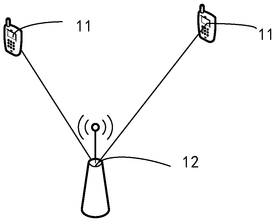
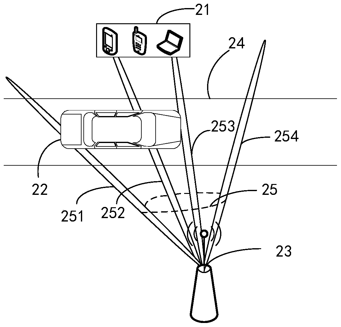
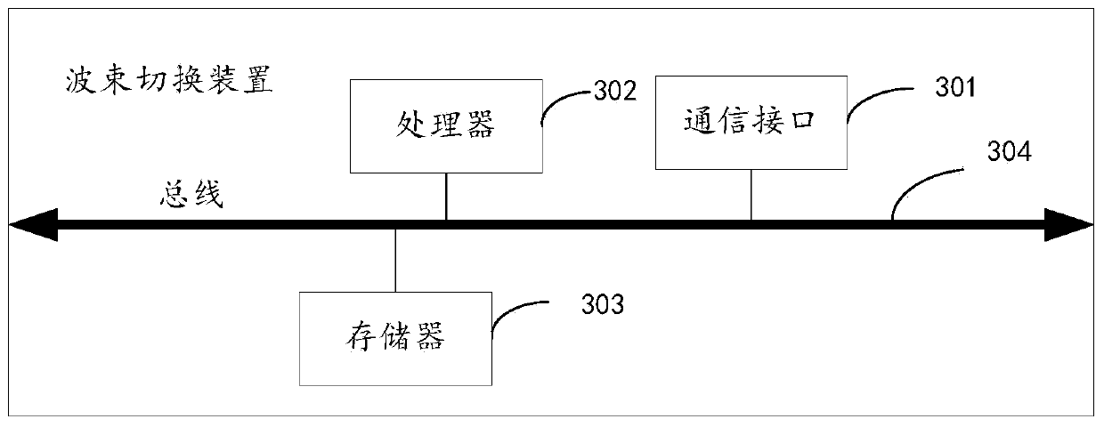
technical field [0001] Embodiments of the present application relate to the field of communication technologies, and in particular, to a beam switching method and device. Background technique [0002] Millimeter wave has the advantages of wide spectrum, high reliability, good directivity, and extremely short wavelength, but it also has the disadvantage of not being easy to pass through obstacles. [0003] Currently, after receiving the first beam, the receiving end will measure parameters such as signal to interference plus noise ratio (SINR) and reference signal receiving power (RSRP) of the first beam. Then, the receiving end judges the value of the measured parameter and the value of the preset threshold. When it is determined that the value of the measured parameter is smaller than the preset threshold, the receiving end switches from the first beam to the second beam. [0004] In complex urban road environments, millimeter waves are easily blocked by vehicles / building...

Claims


Application Information

Patent Timeline
Patent Type & Authority Applications(China)
IPC IPC(8): H04B7/06H04B7/08H04B7/0408H04B7/024H04B17/382
CPCH04B7/0695H04B7/088H04B7/0408H04B7/024H04B17/382
Inventor 高帅张忠皓
Owner CHINA UNITED NETWORK COMM GRP CO LTD
Learn More