Poultry offal taking out device

A technology for taking out devices and viscera, which is applied in the field of poultry viscera taking out devices, which can solve the problems of unstable clamping, decreased success rate of clamping, uneven retention, etc., to increase the joint area of ​​clamping, improve the success rate of clamping, The effect of reducing frictional damage

Pending Publication Date: 2020-08-25
JILIN SSK MASCH&ELECTRON CO LTD
20 Cites 3 Cited by

AI-Extracted Technical Summary

Problems solved by technology

If the swing angle is large, it will damage the internal cavity of the bird. If the swing angle is small, some birds have different body shapes. The crop is on the lower right side of the bird body. Due to the obstruction of the head of the gripper arm, the esophagus is likely to be blocked Outside the clamping device, clamping fails, resulting in a decrease in the success rate of clamping
I...

Method used

See Fig. 12,13, open when clamping end right part 32-2 just arrives chest cavity bottom 116 positions, track groove 9-3 keeps level, guarantees that esophagus is in clamping end left part 32-1 and clamping The relative position of the end-right part 32-2 remains unchanged, which reduces the phenomenon of esophageal rupture caused by pulling.
See Fig. 13,18,19,20, clamping end left part 32-1 is provided with groove 39, and its effect has two, and the one, clamp finger 33 position-limiting, play guiding effect, the one is Realize the closure of the left part 32-1 of the clamping end and the right part 32-2 of the clamping end to clamp the gastroesophagus 105, the groove 39 is designed to be transparent, and the purpose is when there is bone residue or meat tissue in the groove 39 , the working extrusion of the clamp finger 33 will not be seriously affected, and the transparent structure is conducive to cleaning.
See Fig. 19,23,24,25, clamping end right part 32-2 opens, flange 44 crosses gastroesophagus 105, then near spine 113, at this moment, hook tooth 43 catches gastroesophagus 105 (see FIG. 24 ), guiding it into the clamping end opening 37. During the upward pulling process of the main body 1 of the device, the glandular stomach 106, the gizzard 107, the heart 108, and the liver 109 (see Figures 9 and 10) are pressed against each other under the action of the main body 1 of the device, and their positions will change, especially in the In the case of irregular food control, the glandular stomach 106, the gizzard 107, and the intestine 114 are larger in size, and the position of the internal organs will change more during the upward lifting process of the device main body 1. In order to ensure the integrity of the liver 109 and the intestine 114, the clamping end 32 adopts a hollow structure to reduce the space occupied by the inner cavity, which can play a positive role. Under the irregular situation of food control, the crop 104 can not all be pulled out the abdominal cavity of the chicken body 100 (seeing Fig. 11e) along with the viscera bag 125, and is often left in the chicken body 100 to be processed by the crop removal machine of the subsequent procedure. According to the requirements of the processing technology, usually, the lung 111 is left in the body cavity. Due to the effect of the hook teeth 43, it is allowed for a part of the left lung and the trachea 110 to be taken out of the cavity. Inspiratory machine treatment of the procedural procedure.
See Fig. 24,25, hook tooth 43 catches gastroesophagus 105, and flange 44 crosses gastroesophagus 105, guides gastroesophagus 105 to enter opening 37 (seeing 19,21,23) correctly, for this reason, the present invention will The bending direction of the flange 44 faces the spine 113, ...

Abstract

The invention relates to a poultry offal taking out device, wherein a device body, a leg separating device, a chest positioner, a wing positioner and a chest pressing device are sequentially installedon a left guide rod and a right guide rod, a rail wheel is arranged between an upper rotary disc and a lower rotary disc, and the left guide rod and the right guide rod are arranged on the outer sideof the rail wheel in parallel and fixed to the upper rotary disc and the lower rotary disc; the track wheel is of a cone structure, a plurality of irregular tracks are arranged on the track wheel inthe circumferential direction, and the device body, the leg separating device, the chest positioner, the wing positioner and the chest pressing device are driven by the upper rotary disc and the lowerrotary disc to rotate circumferentially; and the device main body, the leg separating device, the chest positioner, the wing positioner and the chest pressing device respectively move up and down andswing on the left guide rod and the right guide rod along the tracks on the static track wheels. The clamping fingers capable of freely moving are arranged at the end of the clamping device, openingand closing of the clamping fingers are achieved; and water and gas channels are formed in the clamping device, frictional damage of the clamping device to the liver is reduced, and the gastroesophagus can smoothly enter opening of the clamping fingers.

Application Domain

Poultry eviscerating devices

Technology Topic

EngineeringPhysical therapy +3

Image

  • Poultry offal taking out device
  • Poultry offal taking out device
  • Poultry offal taking out device

Examples

  • Experimental program(1)

Example Embodiment

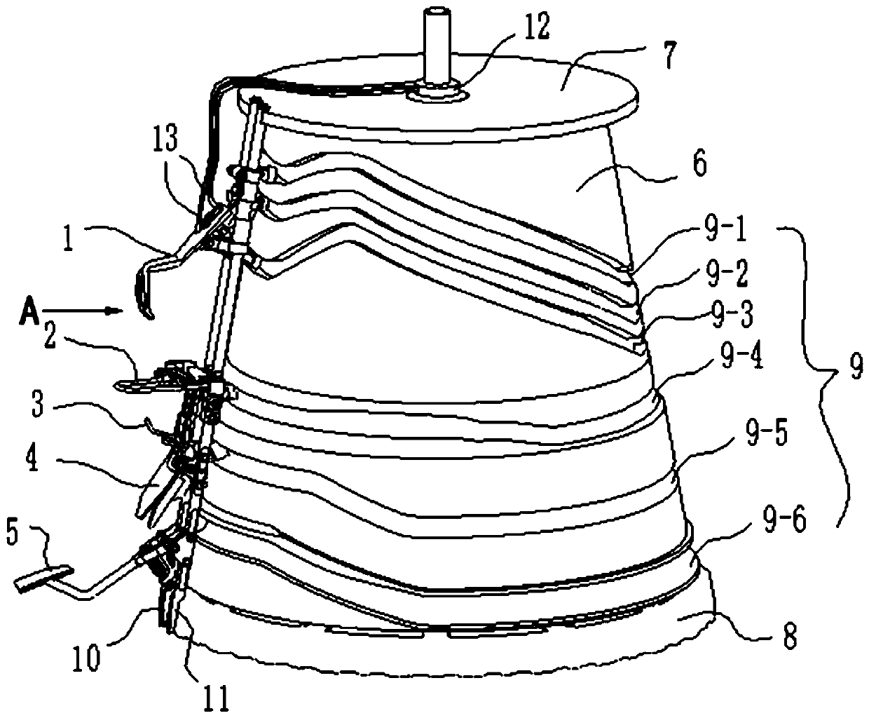
[0081] Studies have shown that chicken breast bones are relatively smooth, have cartilage tissue, have certain rigidity and strength, and can withstand moderate impacts. The chicken legs are on the top and the neck is on the bottom. The two lobes of the chicken liver are unfolded along the sternum of the cavity. The structure of the viscera harvesting device is reasonable, and the path from the inner side of the chicken breast to the junction of the chest cavity and neck is designed appropriately, which will reduce damage to the viscera, especially the liver.
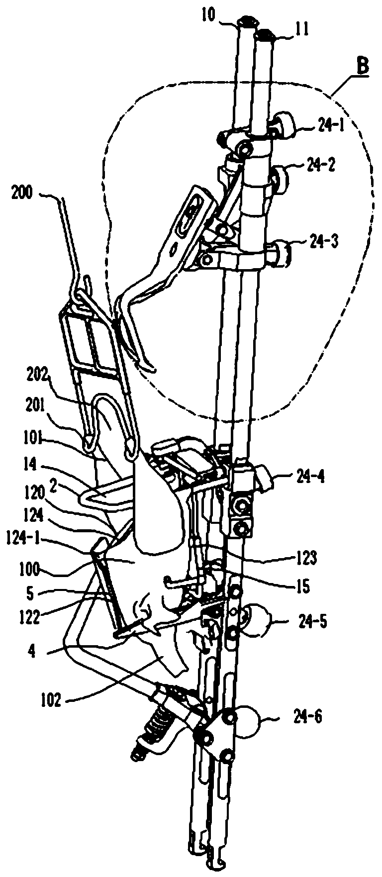
[0082] Studies have shown that when the evisceration device moves downward, filling moderate temperature water between the liver lobe and the sternum will reduce the friction strength between the evisceration device and the liver, reduce the downward movement of the liver with the evisceration device, and reduce the clipping force. Squeeze and crush the edge of the liver lobe with the holding device. During the evisceration process, the temperature of the chicken is usually 38-39°C, and the injection of water at about 20°C can promote the shrinkage of internal organs and the solidification of fat.
[0083] When the clamping device reaches the junction of the chest cavity and the neck, that is, the bottom of the chest cavity, the water and air channels at the end of the viscera extraction device are converted from water to air, and the moving clamping device and air have an effect on the water at the bottom of the chest cavity Force, similar to the effect of "negative water hammer", exerts pressure on and lifts the viscera as a whole, mainly to put pressure on the back of the chicken to fill the gap between the viscera and the mucous membrane of the back, which is conducive to the upward lifting action of the viscera extraction device Goes smoothly, maintaining the integrity of the internal organs.
[0084] In the short state of food control time, the crop, glandular stomach, and gizzard esophagus are all filled with food, and there is water effect, and the gastroesophagus easily slides into the opening of the opened clamping device. The gastroesophagus mentioned here is a small section of the glandular stomach.
[0085] In the state of long-term food control, the crop, glandular stomach, and gastroesophagus lose water, and the surface is sticky, with the effect of water and air, the bonding force between the gastroesophagus and the cavity mucosa is weakened, and it is easy to slide into the opened clamping device in the opening.
[0086] Experiments have shown that in the state of short food control time, the crop is full of food, and it is difficult to pull the crop out from the neck, requiring a strong clamping force to clamp the gastroesophagus. When the viscera harvesting device is lifted upwards, because the crop is filled with food, it is blocked at the neck, and may be broken at the root of the crop. In this case, the gastroesophagus is also filled with food, among which there may be hard food. During the clamping process of hard food, the pinching fingers will damage the gastroesophagus. At the same time, because the crop is filled with food and blocked at the neck, the force on the gastroesophagus at the clamping position increases, and it is easy to break the damaged gastroesophagus.
[0087] Tests have shown that the use of non-metallic fingers is effective in reducing esophageal fractures in occasions where food control is not standardized, as well as chickens, laying hens, etc. The farming of native chickens is close to natural farming, and hard substances are usually added to the feed for laying hens. Therefore, in the application occasions where food control is not standardized, the gastroesophagus is also filled with food, wherein there may be hard food, and during the clamping process of the hard food, the fingers will have a destructive effect on the gastroesophagus. The pinch finger is made of polyurethane or other plastic materials, which can reduce the rigid extrusion of the gastroesophagus, increase the contact area of ​​the pinch finger with the gastroesophagus, and reduce esophageal rupture, which has a positive effect.
[0088] In one embodiment the fingers are self-adjusting in angle. A shaft is used to install the clamp finger on the clamping end, and the clamp finger can swing slightly around the axis, and its swing range is limited to the gap between the clamp finger and the clamping end joint. The size of the gap determines the angle at which the fingers swing. The swinging posture of the pincers caters to the shape of the gastroesophagus. Under normal circumstances, when there is a hard object in the gastroesophagus, the gastroesophagus will automatically deflect to the upper or lower side of the clamp finger axis, and the clamp finger will automatically adjust its posture to clamp the gastroesophagus. When there is a hard object gastroesophagus above the clamp finger shaft, the upper opening of the clamp finger will be enlarged, and the lower opening will be reduced, so that the gastroesophagus will not fall off after being clamped. When there is a hard object, the gastroesophagus is below the clamp finger shaft, the opening of the lower part of the clamp finger will be enlarged, and will form a combination with the lower pin teeth, and the gastroesophagus will be clamped and will not fall off.
[0089] In one embodiment the fingers are self-adjusting. A shaft is used to install the clamping finger on the clamping end of the fixed arm. Driven by the swing arm, the clamping finger can swing largely around the shaft to form a clamping opening capable of accommodating the gastroesophagus. There is a certain amount of clearance between the gripping finger and the shaft connected to the clamping end, which is sufficient to ensure the amount of movement of the gripping finger. When there is a hard object gastroesophagus above the clamp finger, the gap on the left side of the clamp finger shaft decreases, the upper opening of the clamping mouth increases, and the lower opening of the clamping mouth decreases, so that the gastroesophagus can be clamped and will not fall off. When there is a hard object gastroesophagus under the clamp finger, the gap on the right side of the clamp finger shaft decreases, the upper opening of the clamping mouth decreases, and the lower opening of the clamping mouth increases, so that the gastroesophagus can be clamped and will not fall off.
[0090] In one embodiment, the interfinger tooth and the alveolar form a consistent angle, so as to be suitable for different working conditions.
[0091] In one embodiment, there are gaps on both sides between the interfinger teeth and the alveolar, and the size of the gap is suitable for the gastroesophagus. When the food control is not standardized, the gap should be larger.
[0092] In order to ensure the working effectiveness of the gripper, the gripper must be cleaned every working cycle. The cleaning device adopts high-pressure flushing, and high-pressure flushing adopts mature technology. Make sure that the interdigitated teeth, alveolar and related parts are free from bone residue and visceral mucosa.
[0093] See figure 1 , a poultry viscera removal device, the device includes a device main body 1, a leg splitter 2, a wing positioner 3, a chest positioner 4, a chest presser 5, a track wheel 6, an upper turntable 7, a lower turntable 8, and a left guide rod 10. Right guide rod 11; the device main body 1, leg splitter 2, wing positioner 3, chest positioner 4 and chest presser 5 are installed on the left guide rod 10 and right guide rod 11 in sequence; the track wheel 6 is arranged between the upper turntable 7 and the lower turntable 8; the left guide rod 10 and the right guide rod 11 are arranged in parallel on the outer side of the track wheel 6 and fixed on the upper turntable 7 and the lower turntable 8, the diameter of the upper turntable 7 Less than the diameter of the lower turntable 8, the track wheel 6 is a cone structure, and the track wheel 6 is processed with irregular multiple sets of tracks 9 along the circumferential direction; the device main body 1, leg splitter 2, wing positioner 3, The chest positioner 4 and the chest depressor 5 are driven by the rotating discs 7 and 8 to rotate in a circle. The device main body 1 moves up and down on the left guide rod 10 and the right guide rod 11 along the track 9 on the stationary track wheel 6; The chest presser 5 swings up and down on the left guide rod 10 and the right guide rod 11 along the track 9 on the stationary track wheel 6 respectively;
[0094] See figure 2 , the upper hook 200 drives the chicken body 100 to enter the viscera removal device, the chest 122 of the chicken body 100 faces outward, the back 123 faces inward, the abdomen 120 faces upward, and the neck 102 faces downward, and the drumstick 101 is fixed on the hook 200, and the hook 200 The hook crotch 201 at the bottom end is bent towards the chest 122 direction, and the chicken leg 101 is hung in the hook crotch 201 from the inside to the outside.
[0095] The leg splitter 2 stretches the chicken leg 101, and the device main body 1 can pass through the gap 14 of the leg splitter 2 and the gap 202 of the hook.
[0096] The leg splitter 2 is fixed on the left guide rod 10 and the right guide rod 11, and the leg splitter 2 separates the chicken legs 101 to fully expose the abdominal incision 124.
[0097] See figure 2 , image 3 , the wing positioner 3 and the breast positioner 4 are fixed on the left guide rod 10 and the right guide rod 11 together, the breast positioner 4 embraces both sides of the chest 122 of the chicken body 100, and the back 123 leans against the backrest of the wing positioner 3 plate 15.
[0098] See Figure 4 , 5 , the device main body 1 includes a fixed arm 16, a swing arm 17, a swing arm shaft 18, a sliding pin 19, an elevation angle rod 20, an elevation angle shaft 21, an elevation angle rod fixed shaft 22, a swing arm support shaft 23, a roller 24, and an elevation angle upper connection Rod 25, lower connecting rod 26 of elevation angle, upper elevation angle axis 27, lower elevation angle axis 28 and main body sliding seat 29.
[0099] The fixed arm 16 and the swing arm 17 are hinged through the swing arm shaft 18, and the fixed arm 16 and the swing arm 17 are installed on the swing arm shaft 18 in turn.
[0100] The swing arm shaft 18 is installed on the lower connecting rod 26 at the elevation angle, and the swing arm shaft 18 and the main body slide seat 29 are hinged at the swing arm support shaft 23 .
[0101] Described sliding pin 19 and elevation angle bar 20 are hinged at elevation angle bar fixed shaft 22 places; One end of described elevation angle upper link 25 is hinged at elevation angle axis 21 with main body sliding seat 29, and the other end of described elevation angle upper link 25 is hinged with The elevation rod 20 is hinged at the upper elevation axis 27 .
[0102] The main body sliding seat 29 is slidably connected with the left guide rod 10 and the right guide rod 11 .
[0103] The fixed arm chute 30 is arranged on the fixed arm 16 , and the swing arm chute 31 is arranged obliquely on the swing arm 17 .
[0104] Described first roller 24-1 is installed on the connecting rod 25 on the elevation angle, by track groove 9-1 (see figure 1 ) to guide the elevation angle upper link 25 to swing around the elevation angle axis 21, the elevation angle upper link 25 drives the elevation angle rod 20 to swing through the upper elevation angle axis 27, the elevation angle rod 20 drives the sliding pin 19 to move up and down through the fixed shaft 22, and the sliding pin 19 slides on the fixed arm Slot 30 and swing arm chute 31 move inside, because it is arranged obliquely on the swing arm 17, when the slide pin 19 moves up and down, it drives the swing arm 17 to swing left and right, so as to realize the relative opening and closing between the swing arm 17 and the fixed arm 16. closure.
[0105] Described second roller 24-2 is installed on the main body sliding seat 29, by track groove 9-2 (see figure 1 ) to guide the main body 1 of the driving device to move up and down.
[0106] The third roller 24-3 is installed on the lower connecting rod 26 of the elevation angle, and is formed by the track groove 9-3 (see figure 1 ) guides and drives the lower link 26 at the elevation angle to rotate around the swing arm support shaft 23. Realize the upward or downward swing of the swing arm 17 and the fixed arm 16.
[0107] The roller 24 moves along the track groove 9, and under the guidance of the track groove 9, through the joint action of the slide pin 19, the elevation angle rod 20, the elevation angle upper link 25, the elevation angle lower link 26, and the main body sliding seat 29, the swing arm is realized. 17 and fixed arm 16 move up and down, move back and forth, look up or look down, open and close. The movement of the fixed arm 16 and the swing arm 17 entering and withdrawing from the chicken body 100 is realized. The movement track of the clamping end 32 of the device main body 1 and the opening and closing of the swing arm 17 are realized.
[0108] See figure 2 , the leg splitter 2 passes through the chicken leg 101, and under the guidance of the track groove 9-4, compresses the chicken leg 101 to play the role of fixing and stretching the chicken leg 101.
[0109] The chest locator 4 and the wing locator 3 are combined and installed, and under the guidance of the track groove 9-5, the breast side part of the chicken body 100 is held tightly upwards from the bottom.
[0110] image 3 During work, allow the back 123 of the chicken body 100 to lean on the back plate 15 of the wing holder 3, and the wing positioner 3 swings at an angle under the guidance of the track groove 9-5.
[0111] figure 2 Among them, the sixth roller 24-6 on the chest press 5 is in the track groove 9-6 (see figure 1 ), swinging under the guidance of ), pressing the chest 122 frontally.
[0112] The above-mentioned hooks, rollers and track grooves (also known as cam grooves in the mechanical industry) are realized by the mature technology that is often used in this industry.
[0113] Figure 4 Among them, the front end of fixed arm 16 and swing arm 17 is clamping end 32, realizes clamping gastroesophagus 105 (see Figure 9 ).
[0114] The above-mentioned poultry refers to the appearance and internal organs of a chicken.
[0115] See Image 6 , is an embodiment of the clamping end 32, and the clamping end 32 has a clamping end left part 32-1 and a clamping end right part 32-2.
[0116] See Figure 7 , Figure 13 , the right part 32-2 of the clamping end is provided with a clamp finger 33, and the clamp finger 33 is fixed on the swing arm 17 with a clamp finger shaft 34. There is a clamp finger gap 35 between the clamp finger 33 and the swing arm 17, and the clamp finger 33 is The finger pinch shaft 34 is an axis that freely swings in the pinch finger gap 35 . When the swing arm 17 is pulled apart along the opening direction 36 , the clamping end left part 32 - 1 and the clamping end right part 32 - 2 create an opening 37 for receiving the gastroesophageal tube 105 . The top of the clamping finger 33 is provided with a bar 38 , which is inserted into the groove 39 of the left part 32 - 1 of the clamping end, and the bar 38 slides in the groove 39 .
[0117] See Figure 7 , Figure 8 , said clamp finger 33 is provided with convex teeth 40, when the swing arm 17 is closed along the closing direction 41 (see Figure 8 ), the protruding tooth 40 of the clamping finger 33 is embedded in the groove 39 of the left part 32-1 of the clamping end; the protruding tooth 40 and the groove 39 have angles corresponding to each other, and there is no acute angle, and they will not bite to death after closing.
[0118] See Figure 7 , Figure 13 , the lower end of the clamp finger 33 is provided with a locking hook 42, the locking hook 42 is embedded in the groove 39 in a sliding manner, and has no acute angle, and the right part 32-2 of the clamping end will not bite the groove 39 after closing.
[0119] See Figure 7 , 13 , 19, 22, 23, 24, 25, the left part 32-1 of the clamping end is provided with hook teeth 43, and the hook direction of the hook teeth 43 is towards the spine 113, and its effect is basically similar to that of the hook teeth in the US4435878 embodiment. The spine 113 guides, hooks and guides the gastroesophageal tube 105 into the opening 37 .
[0120] See Figure 7 , 13 , 19, 22, 23, 24, 25, the bottom of the clamping end right part 32-2 of the swing arm 17 is provided with a flange 44, and the bending direction of the flange 44 faces away from the spine 113, and its function is different from that of the hook teeth in the US4435878 embodiment , mainly using the spine 113 guide (see Figure 22 , Figure 23 , Figure 25 ), the gastroesophagus 105 is not hooked, and the gastroesophagus 105 is crossed, so that the gastroesophagus 105 enters the opening 37 of the clamping end 32 smoothly.
[0121] See Figure 9 , the chicken body 100 is the hanging position of the visceral working state. The location of the internal organs is an approximate location, and the location of the internal organs of different chicken breeds is somewhat different. Wherein, the anus 115 has been cut by a rotary cutter and separated from the skin, internal fat and other tissues of the abdomen 120 . The larger shape of the crop 104 is an exaggerated drawing, used to express the irregular situation of food control. Gastroesophagus 105 is an anatomical term specifically named in the present invention, and gastroesophagus 105 is a section of esophagus between the crop 104 and the glandular stomach 106, and is the clamping position specified by the clamping end 32 of the present invention. Before evisceration is performed, the anterior esophagus 103 and trachea 110 should be severed.
[0122] See Figure 9 , 10 From the perspective of the chest 122 of the chicken body 100 to the back 123, the crop 104 of the chicken is on the right side of the bottom 116 of the chest cavity, and the gastroesophagus 105 passes through the spine 113 obliquely to the left and is connected with the glandular stomach 106 of the left chest cavity. Therefore, the timing at which the clamping end 32 reaches the chest bottom 116 should be controlled, and the timing at which the clamping end 32 opens and closes also needs to be controlled.
[0123] See Figure 19 , 23 , 24, 25, the right part 32-2 of the clamping end is opened, and the flange 44 crosses the gastroesophagus 105, and then approaches the spine 113. At this time, the hook teeth 43 catch the gastroesophagus 105 (see Figure 24 ), guiding it into the clamping end opening 37. During the upward pulling process of the device main body 1, the glandular stomach 106, the gizzard 107, the heart 108, and the liver 109 (see Figure 9 , 10 ) under the action of the main body 1 of the device, squeeze each other, and the position will change, especially in the case of irregular food control, the glandular stomach 106, gizzard 107, and intestine 114 are relatively large in shape, and they are lifted up by the main body 1 of the device. During the pulling process, the position of internal organs will change more. In order to ensure the integrity of the liver 109 and the intestine 114, the clamping end 32 adopts a hollow structure to reduce the space occupied by the inner cavity, which can play a positive role. Under the situation that food control is not standardized, crop 104 can not all pull out chicken body 100 abdominal cavity along with viscera bag 125 (see Figure 11 e) is often left in the chicken body 100 to be processed by the decapsler of the subsequent process. According to the requirements of the processing technology, usually, the lung 111 is left in the body cavity. Due to the effect of the hook teeth 43, it is allowed for a part of the left lung and the trachea 110 to be taken out of the cavity. Inspiratory machine treatment of the procedural procedure.
[0124] The viscera bag 125 of the present invention is a collection of viscera taken out from the chicken carcass 100, and is usually not in a scattered state.
[0125] Figure 11 is the working process of the clamping end 32. The premise of visceral extraction is that the anus 115 has been cut by a rotary cutter and separated from the skin, internal fat and other tissues of the abdomen 120 , and the anus 115 and a section of intestine 114 are hung on the cocktail 121 .
[0126] See Figure 11 a, after the chicken body 100 is positioned, the clamping end 32 starts to descend.
[0127] See Figure 11 b, 11c, the clamping end 32 enters the abdomen 120 from the position of the anus 115 . The gripping end 32 moves along the direction of the arrow from the abdominal incision 124 to the chest tip 124 - 1 of the incision, mainly to lift the adhesion between the skin and mucous membrane of the abdomen 120 and the intestine 114 . It is helpful for the intestine 114 to exit the cavity smoothly when the clamping end 32 is lifted.
[0128] Figure 11 d, the clamping end 32 reaches the position of the chest bottom 116 along the chest inner wall 117, the right part 32-2 of the clamping end is opened, and the flange 44 crosses the gastroesophagus 105 (see Figure 25 ), the hook teeth 43 and the flange 44 support the clamping end 32 against the spine 113. At this time, the hook teeth 43 hook the gastroesophagus 105 (see Figure 24 ), the clamping end 32 starts to lift up, and guides the gastroesophagus 105 into the opening 37 of the clamping end, the right part 32-2 of the clamping end is closed, and the gastroesophagus 105 is clamped.
[0129] Figure 11 e, the clamping end 32 is lifted up to remove the viscera bag 125 from the cavity of the chicken body 100 to complete a viscera removal process.
[0130] See Figure 12 , 13 , when the right part 32-2 of the clamping end just reaches the position of the bottom of the chest cavity 116, it opens, and the track groove 9-3 remains horizontal to ensure that the esophagus is in the relative position between the left part 32-1 of the clamping end and the right part 32-2 of the clamping end. The position remains unchanged, reducing the phenomenon of esophageal rupture caused by pulling.
[0131] Figure 13 It is a longitudinal sectional view of the opened state of the clamping end right part 32-2. The swing arm 17 is provided with a clamp finger 33, the clamp finger 33 is fixed on the swing arm 17 with a clamp finger shaft 34, there is a clamp finger gap 35 between the clamp finger 33 and the swing arm 17, and the clamp finger 33 is formed by the clamp finger shaft 34. The axis swings in the gap 35 between the fingers. When the swing arm 17 is pulled apart along the opening direction 36, an opening 37 for accommodating the gastroesophagus 105 is produced between the left part 32-1 of the holding end and the right part 32-2 of the clamping end, and the top of the clamping finger 33 is provided with The blocking bar 38 is inserted into the groove 39 of the end part 32 - 1 , and the blocking bar 39 can slide in the groove 39 .
[0132] Figure 14 , 15 is a schematic view of the clamping end 32 in a closed state. In the case of irregular food control, the clamp finger 33 will automatically adjust its posture to avoid hard materials in the gastroesophagus 105 . When the hard position was close to the stop bar 38, the clamp finger 33 rotated clockwise according to the downward rotation direction 45 (see Figure 16 ), the finger gap 35 decreases above and increases below, clamping the gastroesophagus 105 . When the hard position was close to the lock hook 42, the clamp finger 33 rotated counterclockwise according to the upper rotation direction 46 (see Figure 17 ), the finger gap 35 increases above and decreases below, clamping the gastroesophagus 105 .
[0133] See Figure 16 , 17 , 18, 19, 20, 21, the clamp finger 33 is provided with a convex tooth 40, when the swing arm 17 is closed along the closing direction 49, the convex tooth 40 of the clamp finger 33 is embedded in the groove 39 of the left part 32-1 of the holding end in (see Figure 18 ). The protruding teeth 40 and the grooves 39 have angles corresponding to each other, and there is no acute angle, so they will not bite to death after closing.
[0134] See Figure 18 , in the unloaded state, there is no gastroesophagus 105, and the left part 32-1 of the holding end merges with the pincer 33.
[0135] See Figure 19 , 20 , 21, when the clamping end 32 clamps the gastroesophagus 105, the position of the gastroesophageal tube 105 is in the state of the left part 32-1 of the clamping end and the clamping finger 33.
[0136] See Figure 18, the gap 47 and the gap 48, according to the poultry species, the empirical value determined by the breeding period and the feeding state, must be clamped, and the gastroesophagus 105 cannot be pinched off or broken.
[0137] See Figure 13 , 18 , 19, 20, the left part 32-1 of the clamping end is provided with a groove 39, which has two functions, one is to limit the position of the clamping finger 33 and play a guiding role, and the other is to realize the left part 32-1 of the clamping end. 1 and the right part of the clamping end 32-2 are closed to clamp the gastroesophagus 105, and the groove 39 is designed to be transparent, so that when there is bone residue or meat tissue in the groove 39, the working force of the clamp finger 33 is squeezed It will not be severely affected, and the transparent structure facilitates cleaning.
[0138] See Figure 13 , 16 , 17, the lower end of the clip finger 33 is provided with a locking hook 42, and the locking hook 42 is embedded in the groove 39 in a sliding manner. And there is no sharp angle, it will not bite to death after closing. Its function is to prevent the gastroesophageal tube 105 from falling off from the clamping end 32 when the clamping end 32 is pulled upwards.
[0139] See Figure 19 , 22 , the hook teeth 43 and the flange 44 move upward along the spine 113 to play a guiding role, which is beneficial for the gastroesophagus 105 to enter the opening 37 of the clamping end smoothly.
[0140] See Figure 22 , when the clamping end 32 moves upwards, the hook teeth 43 and the flange 44 work together to ride on the spine 113 and stick to both sides of the spine 113, so as to avoid or less clamp the spine 113 when the clamping end 32 is closed.
[0141] See Figure 23 , the hook teeth 43 and the flange 44 cooperate to guide the gastroesophageal tube 105 into the opening 37 . The lower end of the gastroesophagus 105 is a crop 104, and the upper end of the gastroesophagus 105 is a glandular stomach 106 and a gizzard 107.
[0142] See Figure 24 , the hook of the hook teeth 43 on the left part 32 - 1 of the clamping end is bent towards the spine 113 for hooking the gastroesophagus 105 .
[0143] See Figure 25 a, b, the curvature of the flange 44 of the right part 32 - 2 of the clamping end faces away from the spine 113 , and does not hook the gastroesophagus 105 .
[0144] Figure 23 It is a cross-sectional view of the hook teeth 43 and the flange 44 effectively guiding the gastroesophagus 105 into the opening 37 smoothly.
[0145] See Figure 24 , 25 , the hook teeth 43 hook the gastroesophagus 105, the flange 44 crosses the gastroesophagus 105, and guides the gastroesophagus 105 to enter the opening 37 correctly (see 19, 21, 23). For this reason, the present invention makes the bending direction of the flange 44 toward the spine 113, the clamping success rate is improved. This is one of the key points of the present invention. Otherwise, the hook teeth 43 and the flange 44 hook the gastroesophagus 105 at the same time, the gastroesophagus 105 is blocked inside the clamping end 32, the gastroesophageal tube 105 does not enter the opening 37, the clamping end 32 loses the effect of clamping the gastroesophagus 105, and the internal organs Packet 125 will not be effectively removed.
[0146] See figure 2 , 11 d, when the chicken body 100 is positioned, when the clamping end 32 of the chest presser 5 reaches the position of the bottom end 116 of the chest cavity, the pressing force is moderately relaxed to reduce the damage to the rib 112, so that the flange 44 can pass over the gastroesophagus smoothly 105.
[0147] See Figure 26 , 27 , on the fixed arm 16 and on the swing arm 17, be provided with the water-air passage 50 that can pass water and ventilate, when clamping end 32 stretches in the chicken body 100 cavities (see Figure 27 b), the water-air channel 50 starts to pass water. The temperature of the chicken during viscera extraction is usually 38-39°C, injecting water at around 20°C can promote the contraction of the viscera and the solidification of fat. Water and gas are sprayed out from the left injection port 51 of the left part 32-1 of the clamping end and the right injection port 52 of the right part 32-2 of the clamping end through the water-air channel 50, and flow according to the arrow descending direction 53 (see Figure 27 a). The water can lubricate the liver 109 and reduce the frictional damage of the clamping device to the liver 109 . When the clamping end 32 reaches the position of the bottom end 116 of the chest cavity, the bottom end 116 of the chest cavity and its surroundings will be filled with water at the same time. , gizzard and other visceral organs vibrate with the back of the poultry cavity to loosen, relying on the squeezing effect of water, the viscera bag 125 moves up, and when the swing arm 17 is pulled apart, it is ventilated. Under the action of the water hammer, the water vapor flows along the upward direction of the arrow 54, and the organs continue to move up, allowing the organs and the ribs 112 and the tissues of the dorsal medial 118 to loosen (see Figure 17 b), facilitate the removal of organs. Simultaneously, the swing arm 17 is closed to increase the clamping success rate of the clamping end 32 .
[0148] According to the poultry species and breeding period, the medium of the water-air channel 50 is determined, and the medium is supplied in the form of ventilation, water or air-water mixture. It has greatly improved the situation where the food control time does not meet the standard specifications. It is beneficial for the gastroesophageal tube 105 to enter the opening 37 of the clamping end smoothly, thereby improving the success rate of clamping. Under the action of the negative water hammer, water is filled between the mucous membranes, which is conducive to the smooth lifting of the viscera harvesting device 1 and the integrity of the viscera bag 125 is maintained. For applications where food control is not standardized, as well as native chickens, laying hens, etc., the use of non-metallic fingers is effective in reducing esophageal rupture.
[0149] See figure 1 , The upper end of the turntable 7 is provided with a water vapor distribution plate 12. Be connected with fixed arm 16 and swing arm 17 by pipeline 13, supply water and gas by water-air channel 50 (see Figure 26 ). The time and position of water supply and air supply of the water and air distribution plate 12 are corresponding to the time and position of movement of the clamping end 32 . The present invention adopts the conventional water-air distribution plate technology, and the shower head and the multi-purpose faucet in the bathroom have applications, such as the water spray gun structure of Chinese patent 97217974.7, and the high-grade shower nozzle of Chinese patent 99121447.1 all adopt the same principle.
[0150] See Figure 28 , at a suitable position of the device, a high-pressure flushing device 55 is set. When the clamping end 32 is finished each operation, the high-pressure flushing device 55 flushes the clamping end 32 to remove the bone fragments and bone fragments hanging on the clamping end 32 Succulent mucosal tissue, improving the success rate of each job. High-pressure flushing is a broad concept that can take the form of high-pressure water, high-pressure air, or a mixture of air and water. The high-pressure flushing device 55 of the present invention adopts the mature high-pressure flushing technology at present, and the high-pressure flushing device 55 and its pipeline are designed according to the routine, and can be fixed at a suitable position of the equipment.

PUM

no PUM

Description & Claims & Application Information

We can also present the details of the Description, Claims and Application information to help users get a comprehensive understanding of the technical details of the patent, such as background art, summary of invention, brief description of drawings, description of embodiments, and other original content. On the other hand, users can also determine the specific scope of protection of the technology through the list of claims; as well as understand the changes in the life cycle of the technology with the presentation of the patent timeline. Login to view more.

Similar technology patents

Multifunctional luggage case

PendingCN108968262Aeasy accessimprove fit
Owner:嘉兴市驰宇五金股份有限公司

Production process for polymer composite galvanized sheet

InactiveCN108819422AImprove fit
Owner:ANHUI HUABAO BUILDING MATERIAL

Test tube placing rack

PendingCN114832880AImprove fitfixed firmly
Owner:王佳奇

Luggage with composite material integrally formed frame and manufacturing method thereof

ActiveUS20220176612A1increase durabilityimprove fit
Owner:QUEST COMPOSITE TECH LTD

Classification and recommendation of technical efficacy words

  • Improve fit

Pipe welding machine with welding slag cleaning function

Owner:上海中巽科技股份有限公司

Signal sequence processing method and base station

ActiveCN102763389Aimprove fit
Owner:HUAWEI TECH CO LTD

An intelligent customer service management control system

InactiveCN109214666Aimprove fitImprove service efficiency and service quality
Owner:HEFEI HDB INFORMATION TECH CO LTD

Non-woven garment fabric batch cutting treatment method

InactiveCN112281459AImprove fit
Owner:仙桃市科诺尔防护用品有限公司
Why Eureka
Try Eureka