Orthopedic temporary external fixation protector

A technology of external fixation and protective gear, applied in fractures, medical science, etc., can solve problems such as twisting and wearing difficulties, and achieve the effects of preventing tangential torsion, reducing pain, and stabilizing contact

Inactive Publication Date: 2020-08-25
韩晓东
View PDF11 Cites 1 Cited by
  • Summary
  • Abstract
  • Description
  • Claims
  • Application Information

AI Technical Summary

Problems solved by technology

[0004] In order to solve the above problems, the present invention provides a temporary orthopedic external fixation protector to solve the problem that the

Method used


Image

  • Orthopedic temporary external fixation protector
  • Orthopedic temporary external fixation protector
  • Orthopedic temporary external fixation protector

Examples


Embodiment 1

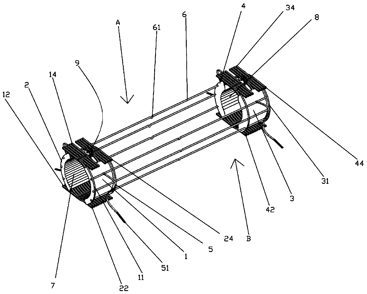
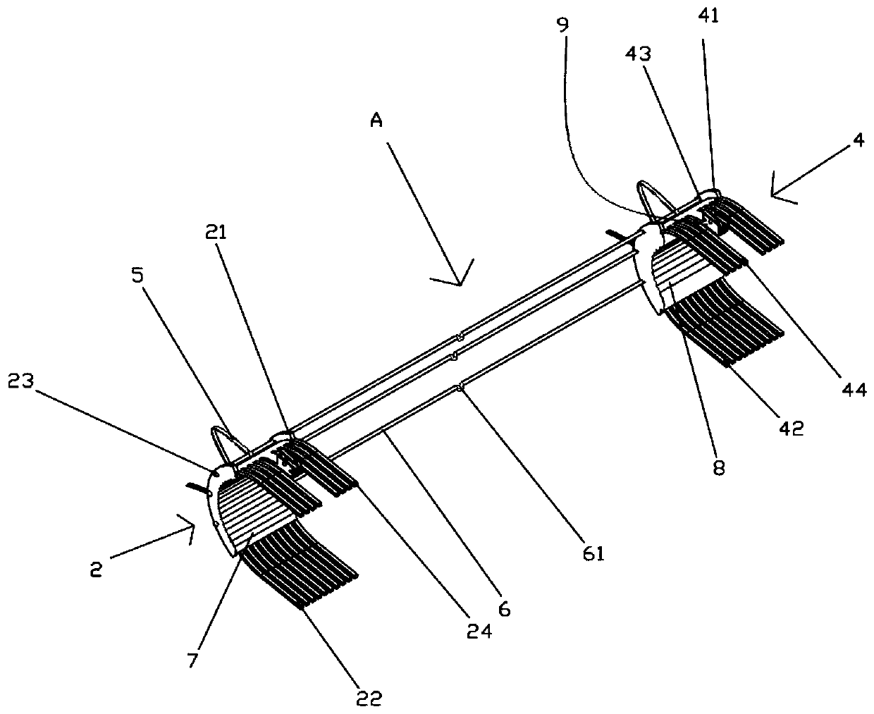
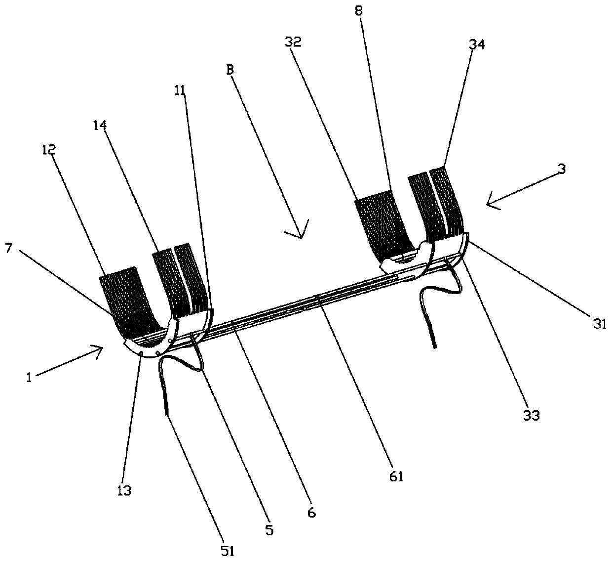
[0024] Example 1, such as Figure 1 to Figure 5 As shown, a kind of orthopedic temporary external fixation protector includes a U-shaped left support structure A and a U-shaped right support structure B. The front end of the U-shaped left support structure A is provided with a leg left guard 2, and the rear end is provided with There is a left ankle guard 4, the front end of the U-shaped right support structure B is provided with a right leg guard 1, and the rear end is provided with a right ankle guard 3, and there are six evenly distributed joints between the leg guard and the ankle guard The positioning columns 6, three of which are located on the U-shaped left support structure A, and the other three are located on the U-shaped right support structure B.

[0025] The bottom of leg left guard plate 2 is provided with several evenly distributed leg left guard plate plane columns 22, and the corresponding position of the bottom of leg portion right guard plate 1 is provided w...

Embodiment 2

[0043] Example 2, such as Image 6 As shown, the difference between this embodiment and Embodiment 1 is that a cylindrical clip 96 is fixed under the bayonet pin 93 to prevent the bayonet pin 93 from being accidentally stuck due to insufficient attraction of the magnetic column 95 to the tail of the bayonet pin 93. Tight case improves the stability of the structure.

[0044] When in use, at first the U-shaped left support structure A and the U-shaped right support structure B are respectively placed on both sides of the injured leg, and the plane column 12 of the right guard plate of each leg is connected with the plane of the left guard plate of each leg. The column 22 is misplaced to the corresponding position, and at the same time pushes towards the injured leg, and rotates the tightening band 5 on the left support plate 22 of the leg and the left support plate 12 of the ankle counterclockwise, bypasses it from the bottom, and inserts it into the corresponding double slot ...


PUM


Abstract

An orthopedic temporary external fixation protector comprises a U-shaped left support structure and a U-shaped right support structure, wherein a left leg protection plate is arranged at the front endof the U-shaped left support structure, a left ankle protection plate is arranged at the rear end of the U-shaped left support structure, a right leg protection plate is arranged at the front end ofthe U-shaped right support structure, a right ankle protection plate is arranged at the rear end of the U-shaped right support structure, positioning columns are connected between the left leg protection plate and the left ankle protection plate and between the right leg protection plate and the right ankle protection plate respectively, the two ends of the two uppermost positioning columns are respectively connected with a tightening belt, the tightening belts are clamped into tightening grooves to achieve tightening of the protector, and when the U-shaped left support structure and the U-shaped right support structure are closed, a fixing platform can be formed at the bottom of the external fixation protector, so that stability of the injured leg is kept.

Description

technical field [0001] The invention relates to the field of medical devices, in particular to an orthopedic temporary external fixation protective gear. Background technique [0002] When a personal accident occurs, patients often cause secondary injuries due to improper emergency treatment, which not only increases the pain of the patient, but also is not conducive to postoperative recovery. Take orthopedic injuries as an example. There is a certain time interval between the patient’s injury and the treatment. At this time, the injured part of the patient needs to be temporarily fixed to prevent the injured part from being injured again. This requires the help of some orthopedic temporary external fixation. protective gear. [0003] The existing orthopedic temporary external fixation protectors mainly adopt full-enclosed protectors, and their shapes are mostly arc-shaped structures similar to human body parts. The medium-sized protectors are more troublesome to wear, and ...

Claims


Application Information

Patent Timeline
IPC IPC(8): A61F5/05
CPCA61F5/05
Inventor 房桂如于纳
Owner 韩晓东
Why Eureka
Try Eureka