Processing device for resin shell of heat dissipating LED lamp tube

A technology for LED lamp tubes and resin shells, which is applied in the direction of grinding drive devices, metal processing equipment, grinding/polishing safety devices, etc., which can solve the problem of increasing user labor, wasting time, and slowing down the progress of LED lamp shell processing and other issues to achieve the effect of saving time, improving efficiency and saving manpower

Inactive Publication Date: 2020-08-25
嘉兴金芯研电子科技有限公司
View PDF8 Cites 2 Cited by
  • Summary
  • Abstract
  • Description
  • Claims
  • Application Information

AI Technical Summary

Problems solved by technology

[0002] LED light shell is a kind of LED accessories, it is a protective cover to better gather light, make light more concentrated, and reduce the damage of light to eyes. Most of the existing LED light tube shells are made of resin. An injection molding machine is required for the processing of the shell. After the injection molding machine is completed, some mold splicing marks will be left on the finished product, which needs to be polished. In fact, the production process is often manually polished, which slows down the LED lights. The progress of shell processing wastes a lot of time, increases the workload of users, and increases the cost of lamp shell processing. Therefore, we propose a heat-dissipating LED lamp tube resin shell processing device

Method used


Image

  • Processing device for resin shell of heat dissipating LED lamp tube
  • Processing device for resin shell of heat dissipating LED lamp tube
  • Processing device for resin shell of heat dissipating LED lamp tube

Examples


Embodiment Construction

[0018] The following will clearly and completely describe the technical solutions in the embodiments of the present invention with reference to the accompanying drawings in the embodiments of the present invention. Obviously, the described embodiments are only some, not all, embodiments of the present invention. Based on the embodiments of the present invention, all other embodiments obtained by persons of ordinary skill in the art without making creative efforts belong to the protection scope of the present invention.

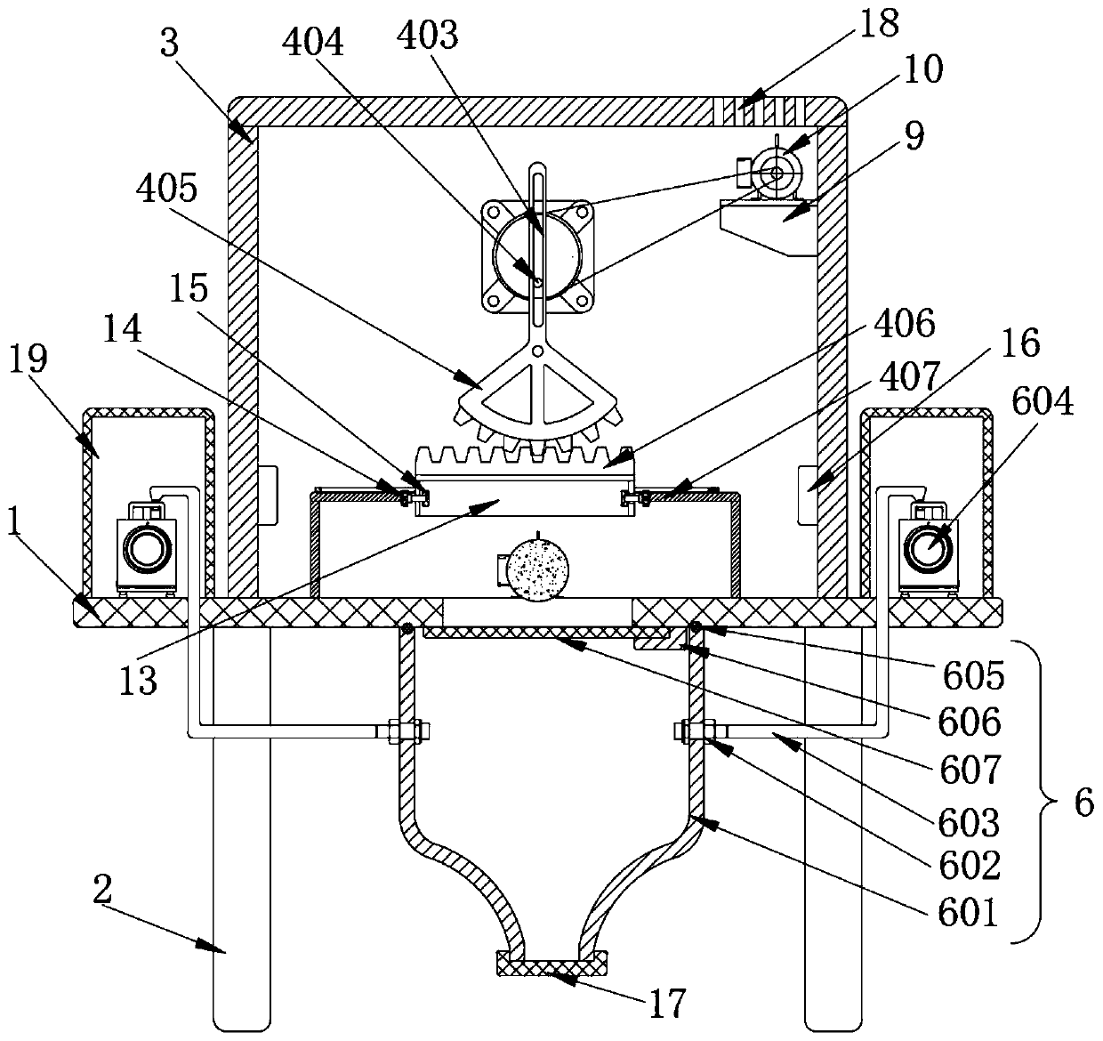
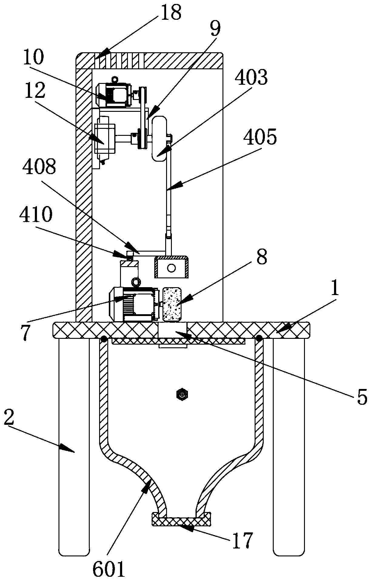
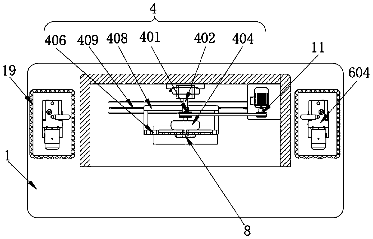
[0019] see figure 1 , a heat-dissipating LED lamp tube resin casing processing device, comprising a table top 1, table legs 2 and a casing 3, the lower surface of the table top 1 is symmetrically fixedly connected with the table legs 2, and the upper part of the table top 1 is fixedly connected with the casing 3, so The inner wall of the shell 3 is provided with a reciprocating mechanism 4, the middle part of the table top 1 is provided with a discharge port 5...


PUM


Abstract

The invention discloses a processing device for a resin shell of a heat dissipating LED lamp tube. The device comprises a table board, table legs and a shell. The table legs are symmetrically and fixedly connected to the lower surface of the table board, the shell is fixedly connected to the upper part of the table board, a reciprocating mechanism is arranged on the inner wall of the shell, an unloading port is formed in the middle of the table board, an attle collecting mechanism is fixedly connected to the lower surface of the table board, a polishing motor is fixedly connected to the upperpart of the table board through a bolt, the polishing motor is located at an edge of the unloading port, a polishing wheel is fixedly connected to an output shaft of the polishing motor, the polishingwheel is located right above the unloading port, a bracket rack is fixedly connected to a side surface of the inner wall of the shell, a driving motor is fixedly connected to the upper surface of thebracket rack through a bolt, and a driving wheel is fixedly connected to an output end of the driving motor. The processing device is simple in structure, higher in efficiency, low in cost, more convenient to disassemble and use and higher in practicality.

Description

technical field [0001] The invention relates to the field of LED lamp tube resin shell processing devices, in particular to a heat dissipation LED lamp tube resin shell processing device. Background technique [0002] LED light shell is a kind of LED accessories, it is a protective cover to better gather light, make light more concentrated, and reduce the damage of light to eyes. Most of the existing LED light tube shells are made of resin. An injection molding machine is required for the processing of the shell. After the injection molding machine is completed, some mold splicing marks will be left on the finished product, which needs to be polished. In fact, the production process is often manually polished, which slows down the LED lights. The progress of shell processing wastes a lot of time, increases the workload of users, and increases the cost of lamp shell processing. Therefore, we propose a heat-dissipating LED lamp tube resin shell processing device. Contents of...

Claims


Application Information

Patent Timeline
IPC IPC(8): B24B5/04B24B5/50B24B9/20B24B55/06B24B47/16B24B41/06B24B41/00B24B41/02
CPCB24B5/04B24B5/50B24B9/20B24B41/005B24B41/02B24B41/067B24B47/16B24B55/06
Inventor 金波
Owner 嘉兴金芯研电子科技有限公司
Why Eureka
Try Eureka