Positioning clamp for U-shaped bending plate

A technology for positioning fixtures and bending plates, which is applied in metal processing and other directions, and can solve problems such as processing errors and slow processing speeds

Pending Publication Date: 2020-08-25
ANHUI TATFOOK TECH CO LTD
View PDF0 Cites 0 Cited by
  • Summary
  • Abstract
  • Description
  • Claims
  • Application Information

AI Technical Summary

Problems solved by technology

[0004] Therefore, the present invention provides a positioning fixture for U-shaped bending plates. When processing U-shaped bending plates in the prior art, it is necessary to manually clamp the workpiece repeatedly to process the two bending fins of the workpiece. Not only the processing speed Slow and easy to cause processing errors due to workers' mistakes

Method used


Image

  • Positioning clamp for U-shaped bending plate
  • Positioning clamp for U-shaped bending plate
  • Positioning clamp for U-shaped bending plate

Examples


Embodiment 1

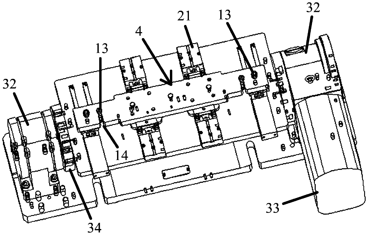
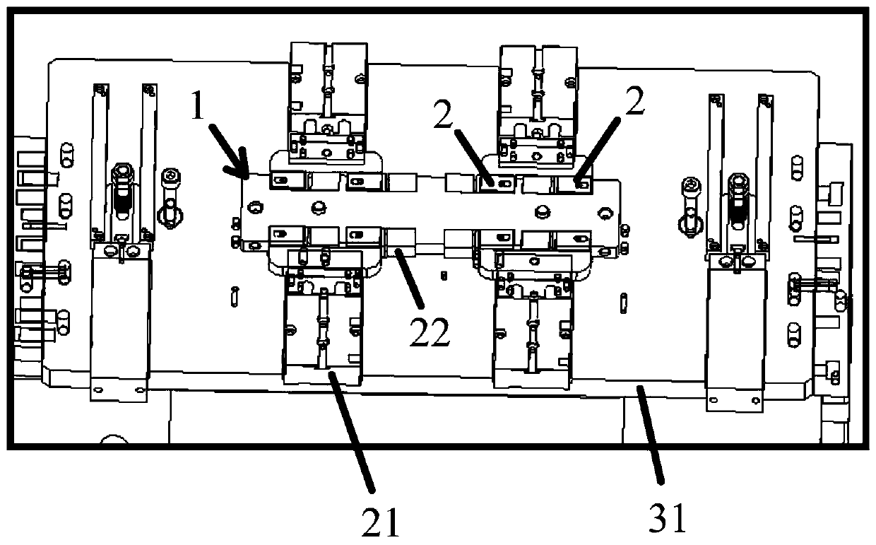
[0057] A positioning fixture for U-shaped bending plates provided in this embodiment, such as Figure 1 to Figure 3 shown, which includes:

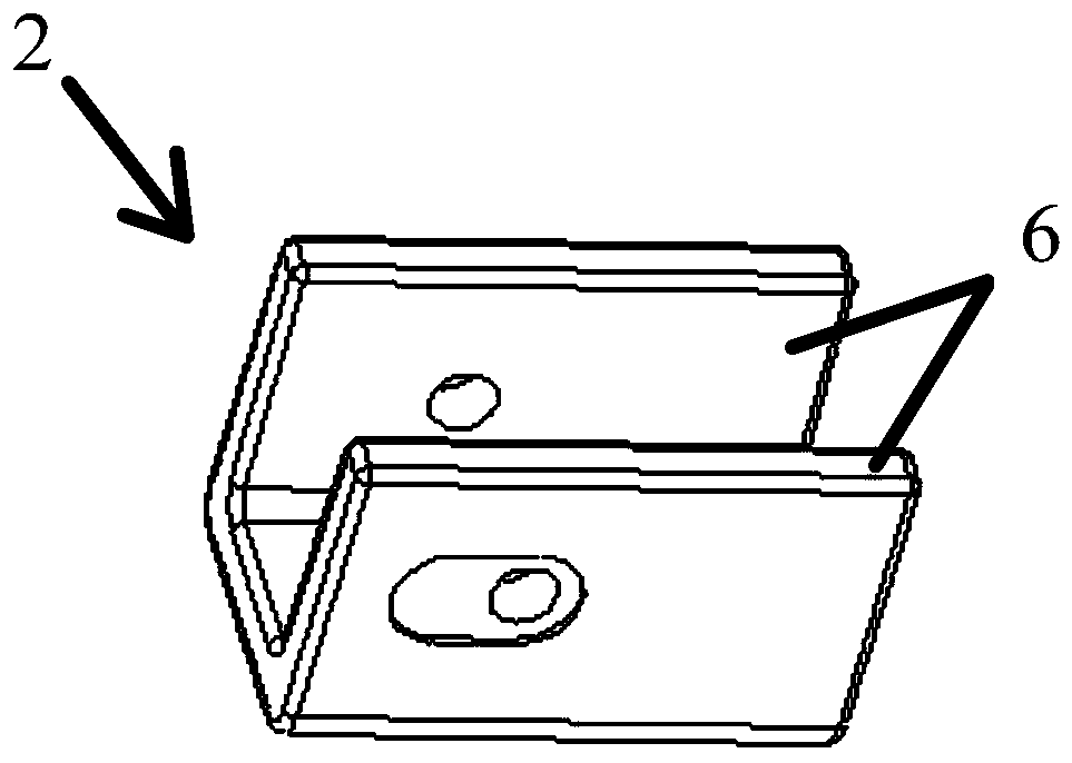
[0058] The clamping fixture 1 is arranged on the fixed base plate 31; the outer contour edge of the clamping fixture 1 is provided with a clamping part 3 for inserting the U-shaped bending plate 2, and the clamping part 3 is for accommodating The groove of the U-shaped bending plate 2; there is a sliding gap arranged along the thickness direction of the clamping fixture 1 between the groove and the U-shaped bending plate 2;

[0059] rotating mechanism, such as Figure 5 As shown, it is connected with the clamping fixture 1 to drive the clamping fixture 1 to rotate on the same horizontal plane to convert the front and back positions of the clamping fixture 1; the rotating mechanism includes: respectively arranged on The fixed seats 32 at both ends of the fixed base plate 31, and the fifth drive source 33; the fixed base 32 is provided wi...


PUM


Abstract

The invention relates to a positioning clamp for a U-shaped bending plate. The positioning clamp comprises a clamping jig, a rotating mechanism and a pressing mechanism, wherein a clamping part for inserting the U-shaped bending plate is arranged on the edge of the outer contour of the clamping jig; the rotating mechanism is connected with the clamping jig to drive the clamping jig to rotate on the same horizontal plane so as to convert the front surface and the back surface of the clamping jig; the pressing mechanism comprises a first pressing piece arranged on the front surface of the clamping jig and a second pressing piece arranged on the back surface of the clamping jig; the first pressing piece and the second pressing piece push two bending fin plates of the U-shaped bending plate tobe tightly attached to and connected with the clamping jig respectively; and the first pressing piece and the second pressing piece are provided with holes for processing the U-shaped bending plate by processing equipment respectively. By means of the structure, the U-shaped bending plate can be effectively and automatically turned over, so that the problems that the machining speed is low and machining errors are prone to being caused by errors of workers due to the fact that workpieces are repeatedly clamped manually are solved.

Description

technical field [0001] The invention relates to the technical field of fixtures, in particular to a positioning fixture for U-shaped bent plates. Background technique [0002] U-shaped bending plate refers to a plate-shaped workpiece with a U-shaped shape. Since the U-shaped bent plate is bent into a U-shaped structure and processed by injection molding, the U-shaped bent plate and a set of bent fins opposite to it have the problems of difficult control of size deviation and easy deformation. Especially when processing holes on the above-mentioned bent fin plate, it is difficult to accurately locate the U-shaped bent plate through positioning to ensure that the workpiece will not be deformed and the processing efficiency will be guaranteed. [0003] In order to ensure the processing quality of the workpiece when processing U-shaped bending plates. When processing U-shaped bent plates, workers often use the opposite inner surface of the bent fin plate as the positioning ref...

Claims


Application Information

Patent Timeline
Patent Type & Authority Applications(China)
IPC IPC(8): B26F1/16B26D7/02
CPCB26D7/02B26F1/16
Inventor 罗强
Owner ANHUI TATFOOK TECH CO LTD
Why Eureka
Try Eureka