Thermal transfer printing equipment

A technology of thermal transfer and thermal transfer film, which is applied in transfer printing, rotary printing machine, printing and other directions, which can solve the problems of large loss of hot melt powder, clogging of arc screen, and inability to achieve uniform spreading.

Pending Publication Date: 2020-08-25
TAOTECH DIGITAL TECH
View PDF0 Cites 2 Cited by
  • Summary
  • Abstract
  • Description
  • Claims
  • Application Information

AI Technical Summary

Problems solved by technology

This powder spreading mechanism has the following disadvantages: 1. The hot-melt powder is extruded outward along the through hole of the curved mesh screen by the brush, which cannot achieve the effect of spreading the material evenly, resulting in defective products of heat transfer printing products; 2. A large amount of hot-melt powder is attached to the r

Method used


Image

  • Thermal transfer printing equipment
  • Thermal transfer printing equipment
  • Thermal transfer printing equipment

Examples


Embodiment Construction

[0028] This part will describe the specific embodiment of the present invention in detail, and the preferred embodiment of the present invention is shown in the accompanying drawings. Each technical feature and overall technical solution of the invention, but it should not be understood as a limitation on the protection scope of the present invention.

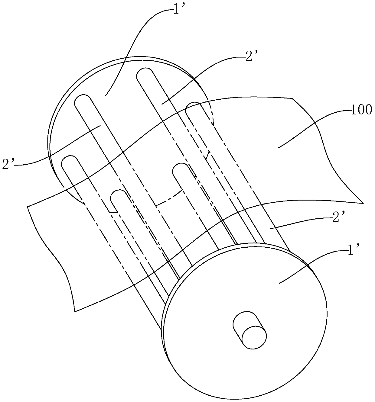
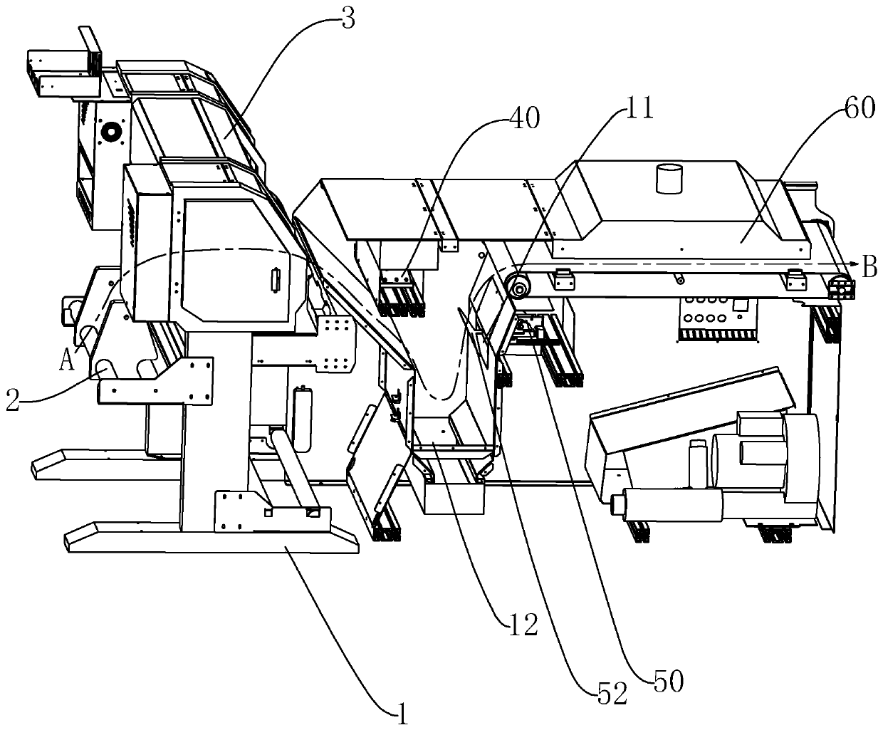
[0029] refer to figure 2 , a kind of thermal transfer equipment of the present invention, comprises frame 1, and described frame 1 is provided with unwinding mechanism 2, printing mechanism 3, powder spreading mechanism 40, powder Clearing device 50 and heating curing device 60, wherein, the conveying direction of thermal transfer film sees figure 2The trajectory shown by the line segment AB; the unwinding mechanism 2 is used to release the thermal transfer film, the printing device is used to print the pattern on the thermal transfer film, and the powder spreading mechanism 40 is used to apply hot melt powder Sprinkle on t...


PUM


Abstract

The invention discloses thermal transfer printing equipment which comprises a rack; an unwinding mechanism, a printing mechanism, a power scattering mechanism, a powder removing device and a heating curing device are sequentially distributed in the conveying direction of a thermal transfer printing film; the powder removing device comprises a mounting base; an impact piece close to or far away from the reverse side of the thermal transfer printing film is movably arranged on the mounting base; an ejection assembly connected with the impact piece to drive the impact piece to impact the reverseside of the thermal transfer printing film in a reciprocating linear manner is arranged on the mounting base and comprises an elastic piece, a movable piece and a driving mechanism; the movable pieceis linked with the impact piece to drive the elastic piece to deform for energy storage, or the movable piece is separated from the impact piece to drive the impact piece to pop up towards the reverseside of the thermal transfer printing film, and the ejection manner can generate larger impact force to the thermal transfer printing film, so that redundant powder is cleared away to further ensurethe quality stability of a following thermal transfer printing product.

Description

technical field [0001] The invention relates to the technical field of thermal transfer printing, in particular to a thermal transfer printing device. Background technique [0002] The thermal transfer printing process generally prints the pattern on the thermal transfer film first, then sprinkles the hot melt powder on the thermal transfer film through the powder spreading mechanism, then removes the excess powder, and then heats the thermal transfer film through the heating and drying device. The molten powder is solidified on the patterned thermal transfer film to obtain the required thermal transfer film, and finally the pattern is transferred to the substrate by heat pressing in the subsequent process. [0003] Such as figure 1 As shown, the current powder removal device for thermal transfer equipment includes two coaxially rotating discs 1', and a plurality of rollers 2' are connected between the two discs 1', and the plurality of rollers 2' Evenly distributed around...

Claims


Application Information

Patent Timeline
IPC IPC(8): B41F16/00
CPCB41F16/0006B41F16/0093
Inventor 不公告发明人
Owner TAOTECH DIGITAL TECH
Why Eureka
Try Eureka