
Code inkjet printing device for pipe or wire

A technology for pipes and wires and inkjet codes, which is applied in printing devices, printing, typewriters, etc., can solve problems such as difficult matching, incomplete printing, low printing quality and efficiency, and achieve high printing quality, high environmental performance, and accurate positioning. Effect

Pending Publication Date: 2020-08-25
SHENZHEN WOER HEAT SHRINKABLE MATERIAL
View PDF0 Cites 2 Cited by
  • Summary
  • Abstract
  • Description
  • Claims
  • Application Information

AI Technical Summary

Problems solved by technology

Because the ink cannot be sealed in this way, the diluent in the ink will volatilize into the air, which does not meet the environmental protection requirements, and the printing quality and efficiency are low. Moreover, for pipes with small diameters, the printing surface of the printing wheel and the outer surface of the pipe The surface is difficult to match, which can easily lead to incomplete printing

Method used


Image

  • Code inkjet printing device for pipe or wire
  • Code inkjet printing device for pipe or wire
  • Code inkjet printing device for pipe or wire

Examples


Embodiment Construction

[0021] In order to make the object, technical solution and beneficial technical effects of the present invention clearer, the present invention will be further described in detail below in conjunction with the accompanying drawings and specific embodiments. It should be understood that the specific implementations described in this specification are only for explaining the present invention, not for limiting the present invention.

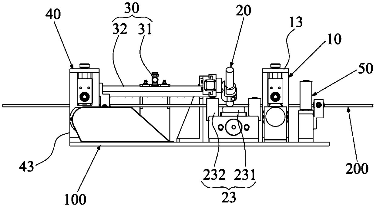
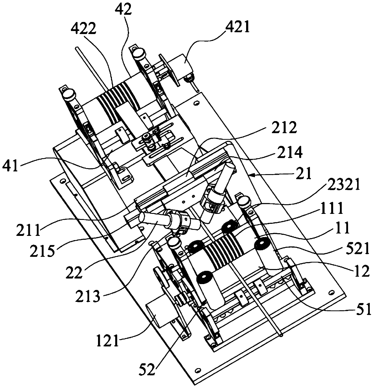
[0022] see figure 1 and figure 2 , The embodiment of the present invention provides a pipe and wire coding device 100 , which includes a meter counting mechanism 10 , a coding mechanism 20 , a drying mechanism 30 and a traction mechanism 40 arranged in sequence along the conveying direction of the pipeline and wire 200 . The meter counting mechanism 10 and the traction mechanism 40 are used for synchronously conveying the pipe wire 200. The meter counting mechanism 10 includes a meter counting roller 11 and a meter counting wheel 12 matched with ...


PUM


Abstract

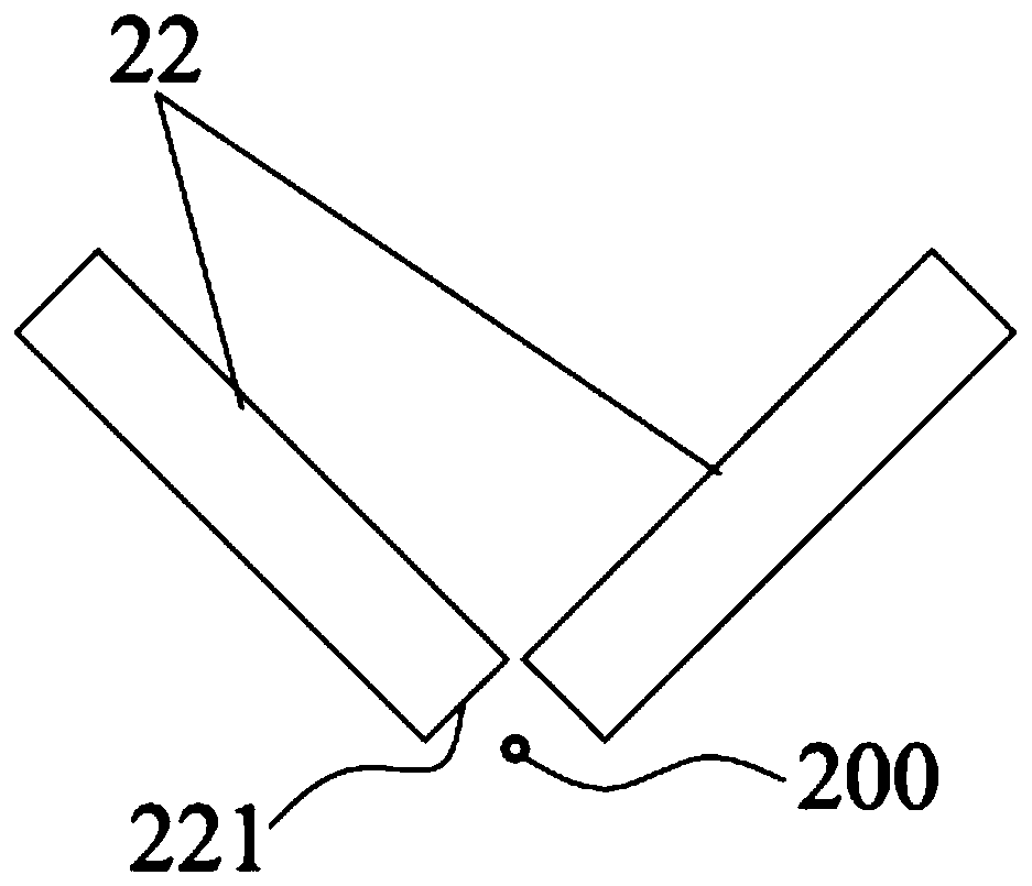
The invention discloses a code inkjet printing device for a pipe or a wire. The code inkjet printing device comprises a meter counting mechanism, a code inkjet printing mechanism, a drying mechanism and a traction mechanism which are sequentially arranged in the conveying direction of the pipe or the wire; the meter counting mechanism and the traction mechanism are used to synchronize the deliveryof the pipe or the wire, the meter counting mechanism comprises a meter pressing wheel and a meter counting wheel matched with the meter pressing wheel, and the traction mechanism comprises a supporting wheel and a synchronous pressing wheel matched with the supporting wheel; and the code inkjet printing mechanism comprises a code inkjet printing frame and at least two code inkjet printing headswhich are arranged on the code inkjet printing frame and connected with a code inkjet printing machine, the at least two code inkjet printing heads are distributed around the periphery of the pipe orthe wire, and the drying mechanism is used to dry the pipe or the wire after code inkjet printing. According to the code inkjet printing device, the code inkjet printing is carried out on the pipe orthe wire through the code inkjet printing heads arranged between the meter counting mechanism and the traction mechanism, so that the jet printing position is accurate, and compared with a type wheel,the environment-friendly performance is higher; and the at least two code inkjet printing heads are arranged around the periphery of the pipe or the wire for code inkjet printing, so that the jet printing area is increased, the code inkjet printing contents can be completely arranged on the surface of the pipe or the wire in a jet printing mode, and the jet printing quality is high.

Description

【Technical field】 [0001] The invention relates to the technical field of pipe and wire production equipment, in particular to a pipe and wire coding device. 【Background technique】 [0002] In the production process of plastic pipes or wires, it is often necessary to print marks on the pipes and wires that move in a straight line. The current commonly used method is to print characters or logos on the surface of the pipe and wire through the printing wheel, and absorb the ink by partially immersing the printing wheel in the ink, and the printing wheel rotates to print the ink absorbed by the lettering part on the pipeline. Because the ink cannot be sealed in this way, the diluent in the ink will volatilize into the air, which does not meet the environmental protection requirements, and the printing quality and efficiency are low. Moreover, for pipes with small diameters, the printing surface of the printing wheel and the outer surface of the pipe The surface is difficult to ...

Claims


Application Information

Patent Timeline
IPC IPC(8): B41J3/407B41J3/44B41J11/00B41J29/20B41J2/01
CPCB41J2/01B41J3/4073B41J3/445B41J11/002B41J11/0045B41J29/20
Inventor 周和平康树峰王玉明张维波周艳飞
Owner SHENZHEN WOER HEAT SHRINKABLE MATERIAL
Learn More