Wind power blade demoulding hoisting fixture and wind power blade demoulding method

A wind power blade, demoulding technology, applied in the direction of safety devices, transportation and packaging, load suspension components, etc., can solve problems such as belt or spreader blade tripping, blade slipping, safety accidents, etc., to improve reliability and safety Reliable and elastic recovery structure, improving the effect of adjusting the clamping force

Active Publication Date: 2022-07-29
ZHUZHOU TIMES NEW MATERIALS TECH
View PDF5 Cites 0 Cited by
  • Summary
  • Abstract
  • Description
  • Claims
  • Application Information

AI Technical Summary

Problems solved by technology

[0002] At present, wind turbine blades are mostly hoisted by slings and ordinary slings. Because the slings or slings cannot effectively clamp the lifted blades, sometimes slings will appear during the air transfer process after the blades are lifted. Or when the sling is disconnected from the lifting blade, once the blade is disconnected and falls from the air, it will damage the blade and hit the equipment or personnel below, causing major safety accidents, which is extremely unsafe
[0003] The existing blade root lifting fixture is a C-shaped seat. Since the distance between the C-shaped seat is generally greater than the thickness of the blade root and does not have a self-locking function, there is a risk of the blade slipping during the demoulding process.
In the self-locking process, if the self-locking force is too large, and the contact surface between the fixture and the wind turbine blade is relatively small, the wind turbine blade, as a kind of FRP material, is relatively brittle and may easily cause crush damage

Method used


Image

  • Wind power blade demoulding hoisting fixture and wind power blade demoulding method
  • Wind power blade demoulding hoisting fixture and wind power blade demoulding method
  • Wind power blade demoulding hoisting fixture and wind power blade demoulding method

Examples


Embodiment Construction

[0030] Attached below Figures 1~4 The embodiments of the present invention will be described in detail.

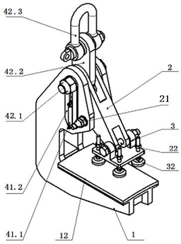
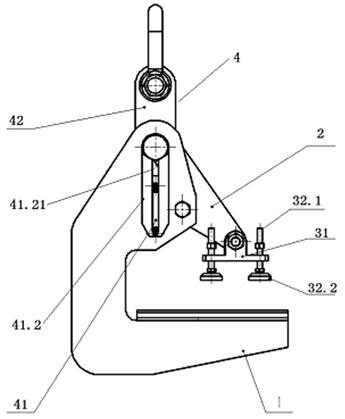
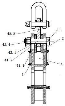
[0031] A wind turbine blade demoulding hoisting fixture includes a C-shaped seat 1, an inclined and swingable pressure block connecting rod 2 mounted on the C-shaped seat 1, and a lower end of the pressure block connecting rod 2 and used to compress the blade on the C-shaped seat 1. The pressure block assembly 3 on the seat 1 is characterized in that it also includes an elastic lifting assembly 4 that can drive the pressure block connecting rod 2 to swing. The elastic lifting assembly 4 is movably mounted on the C-shaped seat 1 and locates the pressure block by elastic force. The initial inclination angle of the connecting rod 2 maximizes the initial distance between the pressure block assembly 3 and the C-shaped seat 1, and the blade extends between the C-shaped seat 1 and the pressure block assembly 3, and is lifted up with the elastic lifting assembly 4. The blade is ...


PUM


Abstract

Wind power blade stripping hoisting fixture, including a C-shaped seat, an inclined and swingable pressure block connecting rod mounted on the C-shaped seat, and a pressure block installed at the lower end of the pressure block connecting rod and used for pressing the blade on the C-shaped seat. The block assembly is characterized in that it also includes an elastic lifting assembly that can drive the connecting rod of the pressure block to swing, the elastic lifting assembly is movably mounted on the C-shaped seat, and the initial inclination angle of the connecting rod of the pressure block is positioned by the elastic force to make the pressure block assembly. The initial distance between the C-shaped seat and the C-shaped seat is the largest, the blade extends between the C-shaped seat and the pressing block assembly, and the blade is gravitationally loaded on the C-shaped seat with the upward lifting of the elastic lifting assembly. The lifting assembly is hoisted and swings downward to reduce the distance between the pressing block assembly and the C-shaped seat and press on the blade. The invention effectively protects the blade from being damaged by clamping during the demolding process, improves the reliability and safety of the clamp, improves the demolding efficiency of the blade, and has a longer service life.

Description

technical field [0001] The invention relates to a wind power blade demoulding hoisting fixture and a wind power blade demolding method, and belongs to the technical field of wind power blade demolding. Background technique [0002] At present, slings and common slings are used to lift the blades of wind turbines. In this way, since slings or slings cannot effectively clamp the hoisted blades, slings sometimes appear when the blades are hoisted and transported in the air. Or if the spreader and the lifting blade are tripped, once the blade is tripped and falls from the air, it will cause damage to the blade and also hit the equipment or personnel below, causing a major safety accident, which is extremely unsafe. [0003] The existing blade root hoisting fixture is a C-shaped seat. Since the distance between the C-shaped seat is generally greater than the thickness of the blade root and does not have a self-locking function, there is a risk of the blade slipping during the dem...

Claims


Application Information

Patent Timeline
Patent Type & Authority Patents(China)
IPC IPC(8): B66C1/10B66C13/04B66C15/00
CPCB66C1/10B66C13/04B66C15/00
Inventor 曹阳俊林能发范阳舟解慧戴明亮张满闯
Owner ZHUZHOU TIMES NEW MATERIALS TECH
Why Eureka
Try Eureka