
Retaining-shoulder-free fastener for urban rail transit

A technology of urban rail transit and fasteners, which is applied in the field of rail fasteners, can solve the problems that the fasteners used in subways cannot meet the small resistance function of the rail at the same time, the fracture, and the constant resistance function of the rail. Application prospects, shortening length, and increasing the effect of lateral load resistance

Pending Publication Date: 2020-08-25
RAILWAY ENG RES INST CHINA ACADEMY OF RAILWAY SCI +3
View PDF0 Cites 3 Cited by
  • Summary
  • Abstract
  • Description
  • Claims
  • Application Information

AI Technical Summary

Problems solved by technology

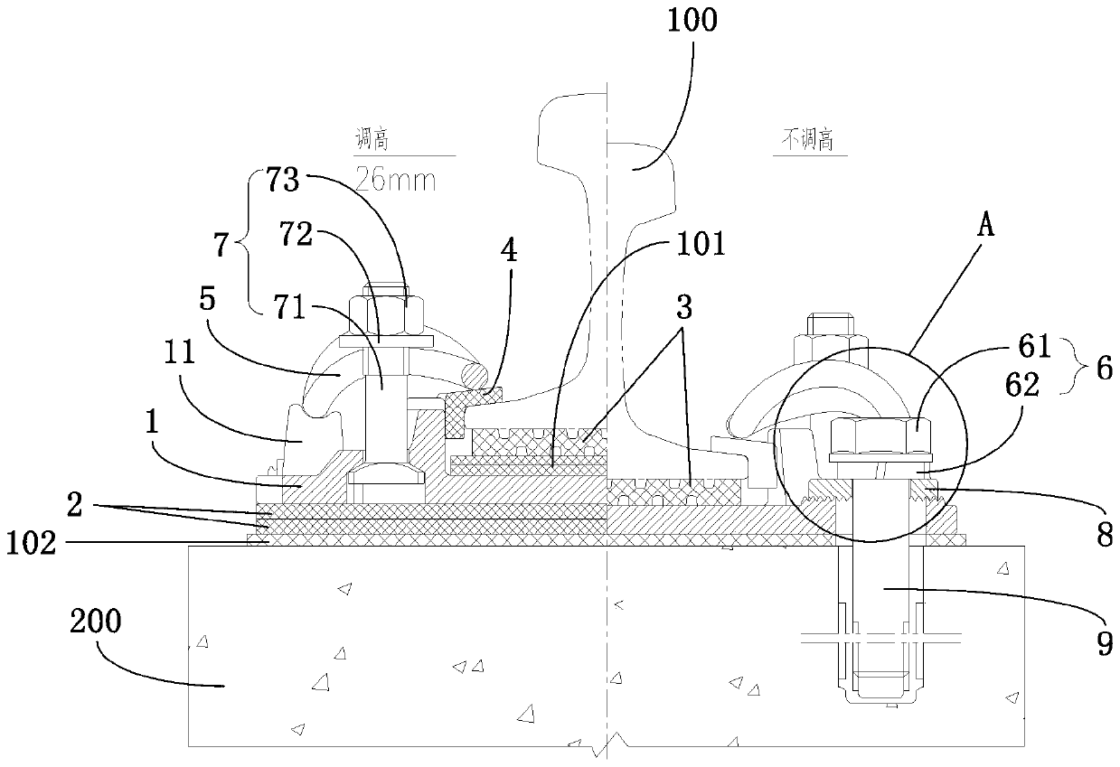
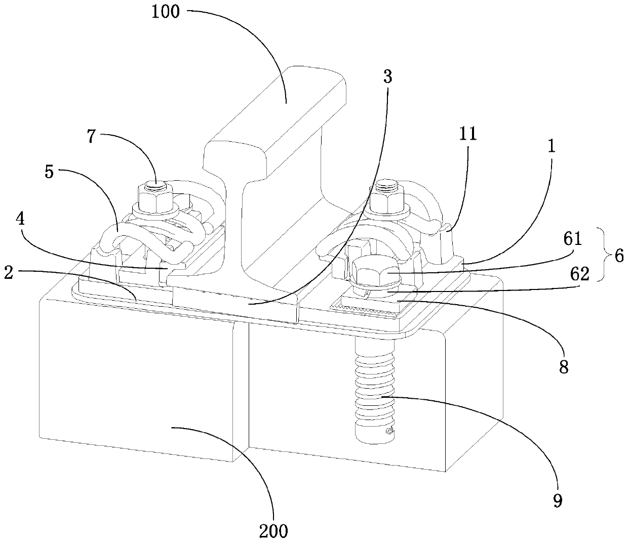
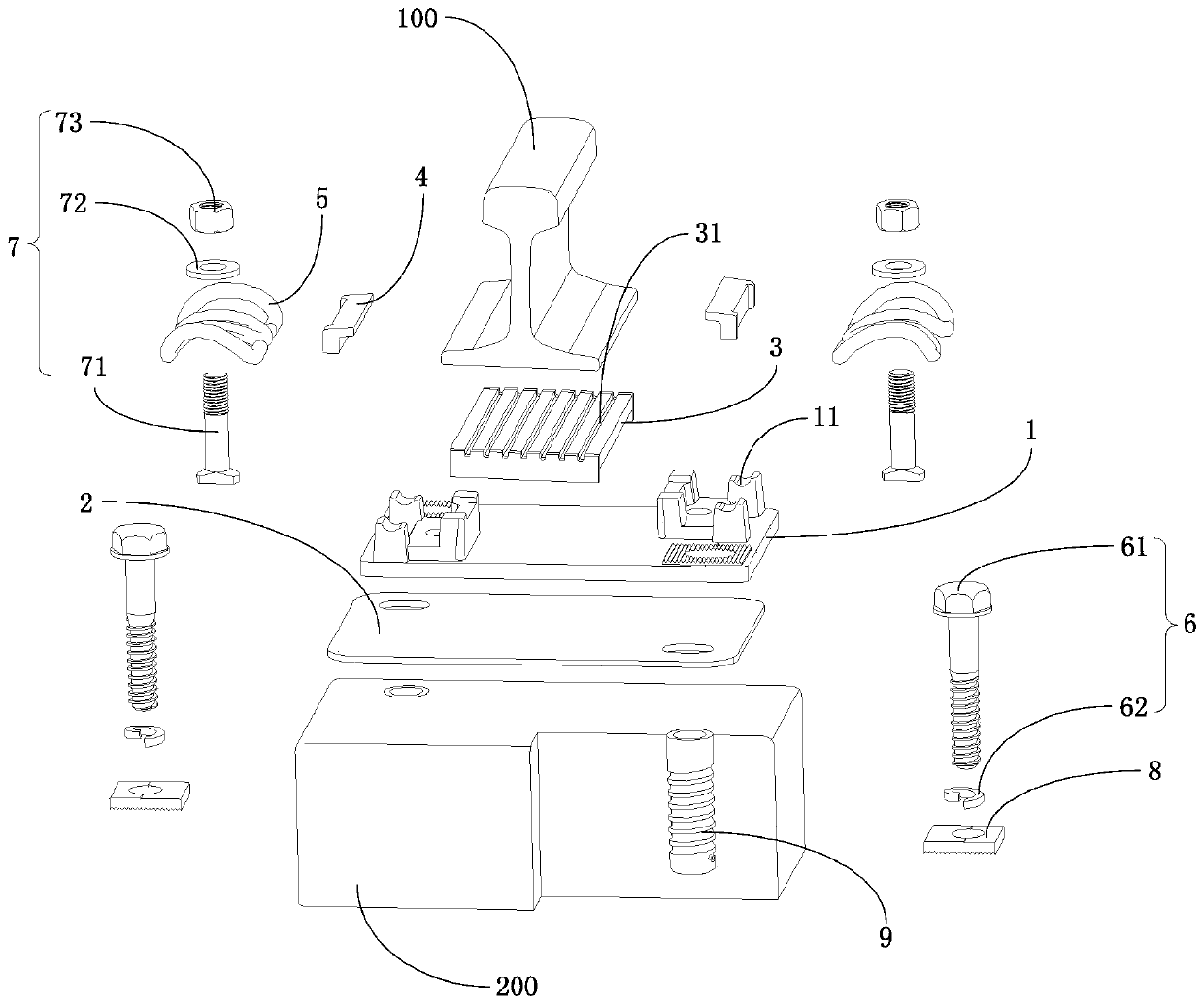
[0005] In view of this, in order to solve the technical problems that the subway fasteners in the prior art cannot simultaneously satisfy the small resistance function of the rail and the constant resistance function of the rail, and the fasteners used for high-speed railways have a large lateral width and are prone to resonate with the wheel-rail excitation frequency and break, etc., The invention provides a method that can realize both the conventional resistance function of the rail and the small resistance function of the rail, and can adjust the height position of the rail by inserting the height-adjusting backing plate under the rail and the iron backing plate, and can effectively avoid Shoulderless fasteners for urban rail transit where elastic strips resonate and break at the wheel-rail excitation frequency

Method used


Image

  • Retaining-shoulder-free fastener for urban rail transit
  • Retaining-shoulder-free fastener for urban rail transit
  • Retaining-shoulder-free fastener for urban rail transit

Examples


Embodiment Construction

[0041] The embodiments of the present invention are described in detail below. Examples of the embodiments are shown in the accompanying drawings, in which the same or similar reference numerals indicate the same or similar elements or elements with the same or similar functions. The embodiments described below with reference to the accompanying drawings are exemplary, and are intended to explain the present invention, but should not be construed as limiting the present invention.

[0042] In the description of the present invention, it should be understood that the terms "upper", "lower", "front", "rear", "left", "right", "vertical", "horizontal", "top", The orientation or positional relationship indicated by "bottom", "inner", "outer", etc. is based on the orientation or positional relationship shown in the drawings, and is only for the convenience of describing the present invention and simplifying the description, rather than indicating or implying the device or The element m...


PUM

PropertyMeasurementUnit
Lengthaaaaaaaaaa
Section diameteraaaaaaaaaa

Abstract

The invention discloses a retaining-shoulder-free fastener for urban rail transit. The fastener comprises an iron base plate, an insulating buffer base plate, an under-rail base plate, an insulating gauge block, an elastic strip, a first bolt fastener, a second bolt fastener, a flat cushion block and an embedded sleeve. The insulating buffer base plate and the iron base plate are sequentially laidon a sleeper top from bottom to top. Bolt through holes are arranged in opposite corners of the insulation buffer base plate and the iron base plate, the flat cushion block is further arranged on theiron base plate, a sawtooth structure is formed at an attaching position of the flat cushion block and the iron base plate, and a first bolt fastener sequentially penetrates through the flat cushionblock, the iron base plate and the insulation buffer base plate to be screwed into the embedded sleeve. Iron bases are arranged at the other opposite corners of the iron base plate, and the second bolt fasteners abut against and fix the elastic strips to the iron bases; and the insulation gauge block is embedded and fixed between a steel rail and the iron bases. The fastener is a great improvementon an existing fastener for subways and fasteners for high-speed rails, and is simple in structure, reasonable in design, more suitable for urban rail transit systems and good in application prospect.

Description

Technical field [0001] The invention relates to the technical field of rail fasteners, and more specifically to a shoulderless fastener for urban rail transit. Background technique [0002] With the rapid growth of the scale of our cities, the rail transit network has also been rapidly developed, and the length of the line and the speed of operation have continued to increase. The existing non-shoulder fasteners for urban rail transit in my country are mainly suitable for lines with speeds of 100km / h and below. At present, the speed of more and more newly-built urban rail lines has generally increased to 120km / h and above. Under these operating conditions The non-shoulder fastener system for urban rail transit is still blank in China. [0003] The current technologies similar to or similar to this patented fastener system mainly include WJ-2 fasteners for subways, WJ-2A fasteners and DTVI2 fasteners, DTVII2 fasteners, and WJ-7 fasteners for high-speed rail. However, WJ-2 type fast...

Claims


Application Information

Patent Timeline
IPC IPC(8): E01B9/38E01B9/62E01B9/68
CPCE01B9/38E01B9/62E01B9/68E01B9/681
Inventor 辛杰方杭玮宋剑伟伍卫凡刘锦辉闫子权龙宏德陈春辉王伟华寇胜宇王健孙林林伍夷祺崔树坤
Owner RAILWAY ENG RES INST CHINA ACADEMY OF RAILWAY SCI
Learn More