
Pavement repairing device for highway engineering

A road surface repair and engineering technology, applied in road repair, roads, roads, etc., can solve the problems of labor and time-consuming, labor-intensive and time-consuming, and the inability to use large mixers and pavers, etc., to improve battery life, The effect of saving labor and time

Inactive Publication Date: 2020-08-25
龙奕宇
View PDF0 Cites 0 Cited by
  • Summary
  • Abstract
  • Description
  • Claims
  • Application Information

AI Technical Summary

Problems solved by technology

In the existing concrete pavement, the method is to clean, pave and smooth the concrete pavement. In the process of repairing the concrete pavement, the proportion of mechanical devices is relatively small, and the proportion of labor is relatively large, which requires a lot of labor and time, resulting in high cost. Increase
When laying repair materials on the damaged pavement, it is necessary to mix the repair materials with water in advance, pour them directly on the ground, and spread them out manually; when the damaged pavement is large, it takes a lot of labor and time; Irregularity and discontinuity of road sections make it impossible to use large mixers and pavers for operations, so there is an urgent need for a road repair device that can continuously and evenly lay repair materials on the damaged road surface

Method used


Image

  • Pavement repairing device for highway engineering
  • Pavement repairing device for highway engineering
  • Pavement repairing device for highway engineering

Examples


Embodiment 1

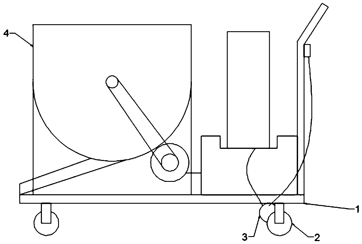
[0043] A road surface repair device for highway engineering of the present invention comprises a base plate 1, four directional pulleys 2 and a drive motor 3 are fixedly connected to the bottom of the base plate 1; the four directional pulleys 2 are facing in the same direction; bottom corners;

[0044] The driving motor 3 is fixedly connected between the two directional pulleys 2 at one end of the bottom of the base plate 1; the driving motor 3 is connected to the directional pulley 2 under control;

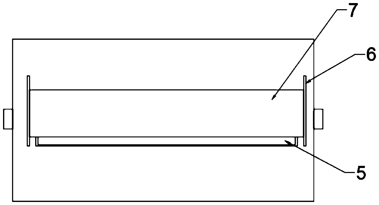
[0045] The mixer 4 is fixedly connected to one end of the upper part of the bottom plate 1; the bottom of the mixer 4 is provided with a material outlet 5 along the length direction of the mixer 4; both sides of the material outlet 5 are vertically fixedly connected with a card slot 6; the upper and lower sides of the two card slots 6 The sliding connection has a baffle plate 7;

[0046]Wherein, base plate 1 can make mixer 4 move more conveniently as the moving carrier of mixer...

Embodiment 2

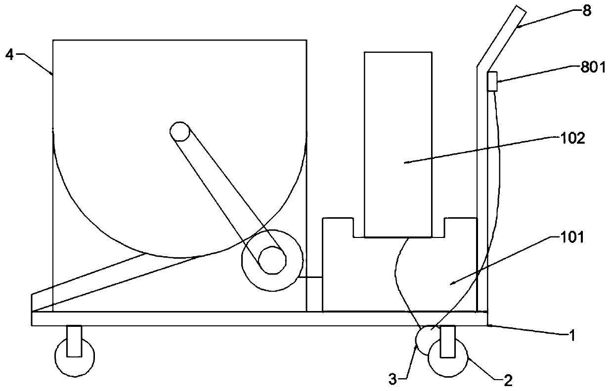
[0050] This embodiment relates to a road surface repair device for highway engineering, which has roughly the same structure as that of Embodiment 1. This embodiment is further optimized on the basis of Embodiment 1: the upper part of the bottom plate 1 is perpendicular to the end away from the mixer 4 and is welded with a handrail 8. The handrail 8 can facilitate the staff to control the direction of the bottom plate 1;

[0051] In order to further optimize a road repair device for road engineering, a speed regulating knob 801 is fixedly connected to the upper part of the handrail 8, and the speed regulating knob 801 is controlled and connected to the drive motor 3 through a circuit, and the drive motor 3 realizes different functions under the control of the speed regulating knob 8. Rotating speed.

[0052] In order to further optimize a road surface repair device for road engineering, a battery base 101 is fixedly connected between the mixer 4 and the handrail 8, and the bat...

Embodiment 3

[0056] This embodiment relates to a road surface repairing device for highway engineering, which has roughly the same structure as that of Embodiment 1. This embodiment is further optimized on the basis of Embodiment 1: the mixer 4 includes a horizontally placed mixing drum 401, a horizontally penetrating The transmission shaft 402 of the mixing drum 401 and the second motor 403 that is rotationally connected with the transmission shaft 402; the transmission shaft 402 is evenly and fixedly connected with the stirring blade 404; the stirring blade 404 is located in the mixing drum 401; the second motor 403 and the transmission shaft 402 Rotate and connect between them by conveyor belt 405;

[0057] Wherein, mixer 4 adopts the horizontally placed mixing drum 401 to make the material outlet 5 at the bottom of the mixing drum 401 longer, and the longer material outlet 5 can expand the coverage area when the repair material is discharged; the second motor 403 drives the drive shaft ...


PUM


Abstract

The invention relates to a pavement repairing device for highway engineering and belongs to the field of pavement repairing. The device comprises a bottom plate and a stirrer. Four directional pulleysand a driving motor are fixedly connected to the bottom of the bottom plate; orientations of the four directional pulleys are consistent; the four directional pulleys are fixedly connected to four corners of the bottom of the bottom plate respectively; the driving motor is fixedly connected between the two directional pulleys at one end of the bottom of the bottom plate; the driving motor is in control connection with the directional pulleys; the stirrer is arranged at one end of an upper part of the bottom plate; a material outlet is arranged in the bottom of the stirrer along a length direction; clamping grooves are arranged in two sides of the material outlet; and a baffle is slidably connected between the two clamping grooves. Compared with the prior art, by using the device of the invention, the bottom plate drives the directional pulleys consistent in orientation to move in one direction through the driving motor, repair materials in the stirrer can be continuously and evenly laid on the ground through the material outlet due to directional movement of the bottom plate, manual stirring and spreading of the repair materials are not needed any more, and a purpose of reducing labor and time is achieved.

Description

technical field [0001] The invention belongs to the field of road surface repairing devices, in particular to a road surface repairing device for highway engineering. Background technique [0002] Due to long-term use or irregular use, dirt pavement often has peeling, dusting, sanding, peeling, pebbles, freeze-thaw, cracks, mesh cracks, pockmarks, and honeycombs. In response to these problems, existing In the technology, pavement repair materials are used to repair the damaged pavement and restore the concrete to its original level. In the existing concrete pavement, the method is to clean, pave and smooth the concrete pavement. In the process of repairing the concrete pavement, the proportion of mechanical devices is relatively small, and the proportion of labor is relatively large, which requires a lot of labor and time, resulting in high cost. Increase. When laying repair materials on the damaged pavement, it is necessary to mix the repair materials with water in advanc...

Claims


Application Information

Patent Timeline
IPC IPC(8): E01C23/09
CPCE01C23/0966
Inventor 龙奕宇
Owner 龙奕宇
Learn More