

High-specific-speed axial flow water turbine with double-inlet volute
A technology with high specific speed and dual inlets, which is applied in the field of water turbines, can solve problems such as optimization of water inlet conditions, and achieve the effects of enhancing velocity components, increasing water flow circulation, and good hydraulic performance
- Summary
- Abstract
- Description
- Claims
- Application Information
AI Technical Summary
Problems solved by technology
Method used
Image

Examples
Embodiment 1
[0094] Take the application of the axial-flow turbine with double-inlet volute proposed by the present invention in a power station as an example. The water head of the power station is 28m, the design flood flow is 18500m3 / s, and the specific speed of the turbine is 600.
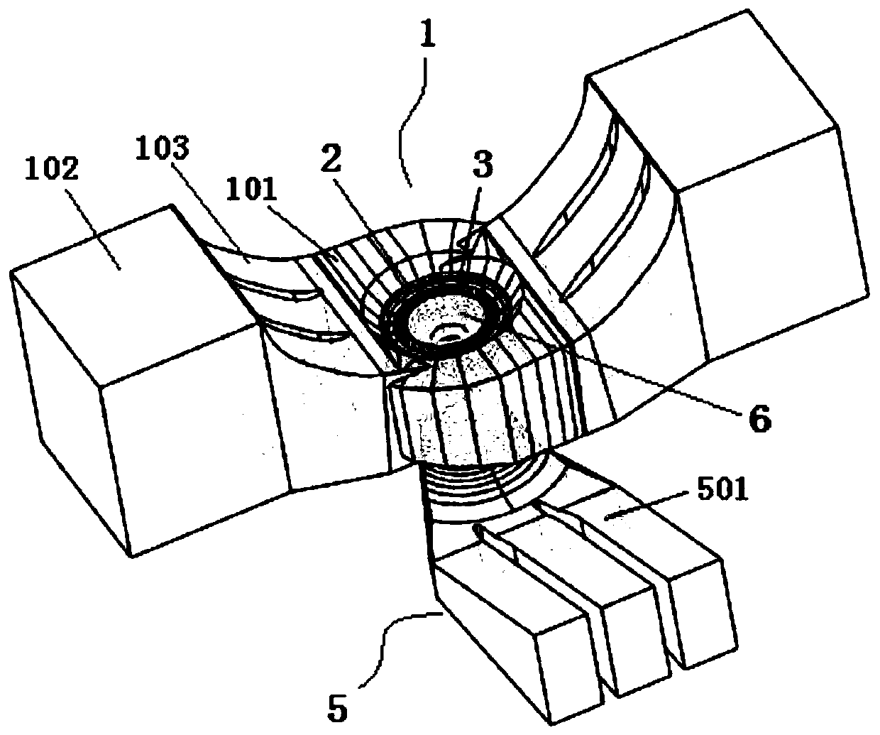
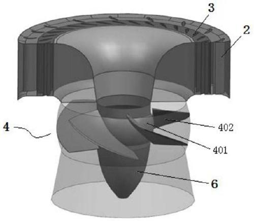
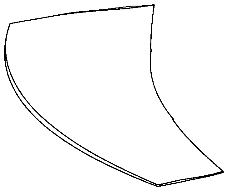
[0095] The optimization parameters of the present invention are: two water inlet pipes are arranged in the circumferential direction of the spiral structure section, the two water inlet pipes are symmetrical about the center of the spiral structure section, and the end of the water inlet pipe is provided with a downward slope section; the ratio of the height to the width of the water inlet pipe is b / a=2.2. The number of movable guide vanes is 32; the blades adopt non-equal thickness twisted structure, and the number is 5 pieces; the draft tube adopts an elbow-shaped draft tube, and the elevation angle of the top plate of the water outlet diffusion section is 11°.
Embodiment 2
[0097] The optimization parameters of the present invention are: two water inlet pipes are arranged in the circumferential direction of the spiral structure section, the two water inlet pipes are symmetrical about the center of the spiral structure section, and the end of the water inlet pipe is provided with a downward slope section; the ratio of the height to the width of the water inlet pipe is b / a=1.9. The number of movable guide vanes is 32; the blades adopt non-equal thickness twisted structure, and the number is 5 pieces; the draft tube adopts an elbow-shaped draft tube, and the elevation angle of the top plate of the water outlet diffusion section is 11°.
Embodiment 3
[0099] The specific application process of the present invention is: the pressurized water flow in the two inlet pipes connected by the double-inlet volute of the present invention generates a center-symmetrical tangential flow in the circumferential direction of the volute structure section through the flow guide pier, so that the water flow A sufficiently large circulation is generated before entering the water guiding mechanism, and the water flowing out of the water guiding mechanism pushes the runner to rotate, thereby converting the energy of the water flow into rotational mechanical energy. The water flow comes out from the runner and is discharged downstream through the draft tube.
PUM
 Abstract
Description
Claims
Application Information