Port power generation device

A technology for power generation devices and ports, applied in wind power generation, hydropower generation, motor generator connectors, etc., can solve the problems of lower overall efficiency, high power consumption cost of the port power system, and the inability to use the impact force of cargo ships entering and leaving the port, etc. Achieve the effect of saving device cost, reducing power consumption cost and simple structure

Inactive Publication Date: 2020-08-25
湖州海明机械科技有限公司
View PDF6 Cites 2 Cited by
  • Summary
  • Abstract
  • Description
  • Claims
  • Application Information

AI Technical Summary

Problems solved by technology

[0004] The purpose of the present invention is to solve the shortcomings in the prior art that the impact force of cargo ships entering and leaving the port cannot be utilized, the power consumption cost of the port power system is relatively high, and the wind power generation device is fixed or needs to be controlled by an electric device, resulting in a decrease in overall efficiency. A port power generation device proposed

Method used


Image

  • Port power generation device
  • Port power generation device
  • Port power generation device

Examples


Embodiment 1

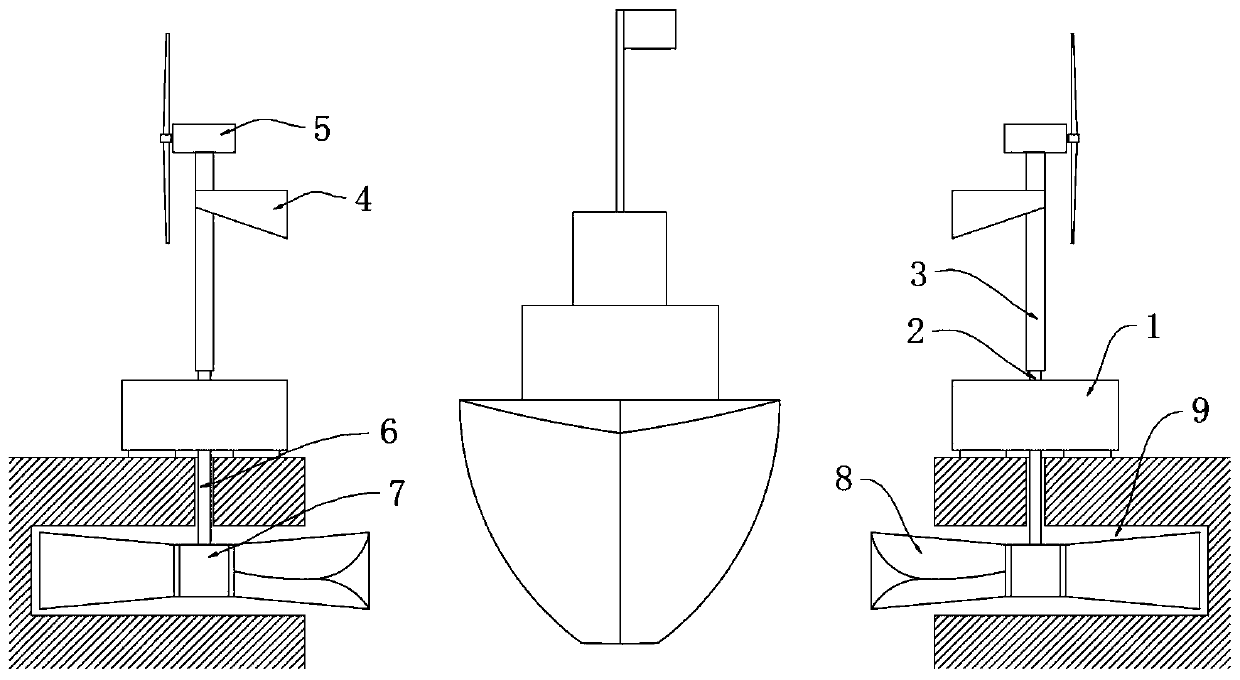
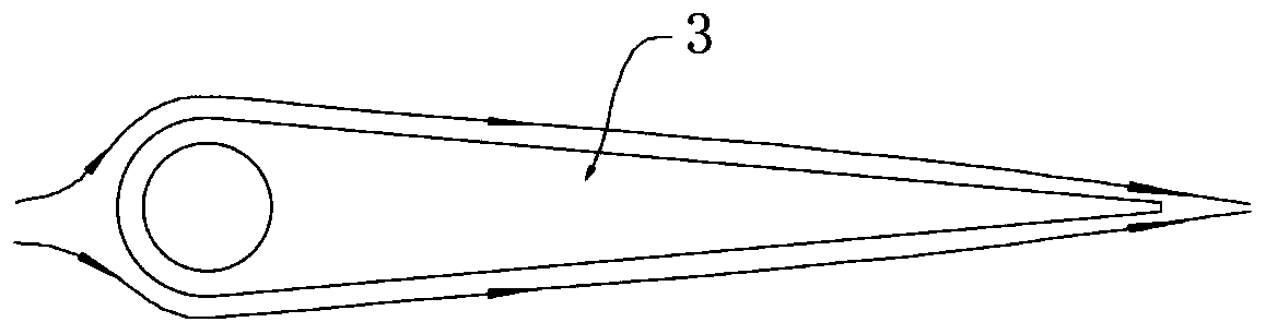
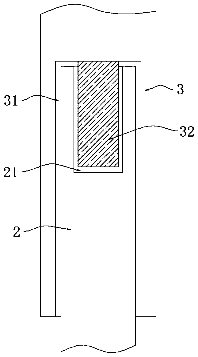
[0028] refer to Figure 1-4 , a port power generation device, including two symmetrically installed power boxes 1 on the ground of the port, each power box 1 is equipped with a connecting rod 2, the upper end of the connecting rod 2 is rotatably provided with a wind rod 3, and the lower end of the wind rod 3 A turn slot 31 is provided, and the bottom of the turn slot 31 is equipped with an electric socket 32. The upper end of the connecting rod 2 is provided with an electric socket 21, and the electric socket 32 ​​is rotated and inserted in the electric socket 21. On the wind rod 3 The wind wing 4 is set, the wind power generator 5 is installed on the wind pole 3, two arc-shaped grooves 9 are symmetrically opened on the bottom surface of the port, and the lower end of each power box 1 is equipped with a shaft tube 6, and the lower end of the shaft tube 6 extends In the arc-shaped groove 9, a shaft core tube 7 is sealed and installed, and a shaft sleeve 8 is arranged on the rot...

Embodiment 2

[0036] refer to Figure 5 , a port power generation device, which is basically consistent with Embodiment 1, the difference is that:

[0037]The wind rod 3 is sealed and rotated on the upper end of the connecting rod 2. The first conductive sheet 301 is installed on the bottom of the rotating groove 31, and the second conductive sheet 201 is installed on the upper end of the connecting rod 2. The rotating groove 31 is filled with conductive liquid 10 ;

[0038] The conductive liquid 10 is a polymer conductive grease. When the connecting rod 2 and the wind rod 3 rotate under the drive of the wind wing 4, the conductive liquid 10 can ensure the stability between the first conductive sheet 301 and the second conductive sheet 201. The electrical connection can also reduce the frictional force between the first conductive sheet 301 and the second conductive sheet 201 , avoiding poor electrical contact caused by long-term friction loss and shortened service life caused by contact s...


PUM


Abstract

The invention discloses a port power generation device. The port power generation device comprises two electric power boxes symmetrically mounted on the ground of a port. A connecting rod is mounted on each electric power box, the upper end of each connecting rod is rotationally sleeved with a wind power rod, a rotating groove is formed in the lower end of each wind power rod, an electric inserting column is mounted at the bottom of each rotating groove, an electric inserting groove is formed in the upper end of each connecting rod, the electric inserting columns are rotationally inserted in the electric inserting grooves, and the wind power rods are sleeved with wind wings. Hydraulic power generation is added on the basis of wind power generation, water flow potential energy caused when freighters enter and leave the port is converted into electric energy to be stored and used, the total power generation efficiency of the device is increased, and the port power consumption cost is reduced; by means of the wind wings, the condition that wind power generation is controlled to be automatically matched with wind directions is not needed, and the wind power generation efficiency is increased; and through the electric inserting columns and the electric inserting grooves, power can be stably supplied by wind power generation, and by means of electric conduction liquid, the service life of the device is prolonged, and the power generation efficiency of the device is improved.

Description

technical field [0001] The invention relates to the field of port power systems, in particular to a port power generation device. Background technique [0002] Freighters are the main means of transportation for larger cargoes. Freighters come in and out of each shipping port every day, and various power system facilities are located in ports to provide convenience for cargo transportation, such as lighting systems, control systems, lighting systems, etc. [0003] Existing ports only have the function of cargo ships entering and leaving the port or only have wind power generation devices, which cannot utilize the energy squeezed by the cargo ships entering and leaving the port, which makes the consumption cost of the port power system generally high, and the wind power generation devices are fixed or need to pass through The electric device controls the orientation of the wind power generation device, and the overall efficiency of power generation is low. Contents of the i...

Claims


Application Information

Patent Timeline
Patent Type & Authority Applications(China)
IPC IPC(8): F03D9/25F03D1/06F03D13/25F03D7/02F03D80/00F03B13/00F03B3/12F03B11/00H01R39/64H01R3/08
CPCF03B3/121F03B3/126F03B11/00F03B13/00F03D1/065F03D7/0204F03D9/008F05B2220/706F03D9/25F03D13/25F03D80/00H01R3/08H01R39/64H01R2201/10Y02E10/20Y02E10/72Y02E10/727
Inventor 顾海明
Owner 湖州海明机械科技有限公司
Why Eureka
Try Eureka