
Pipeline detection robot

A pipeline inspection and robot technology, applied in the direction of supporting machines, pipe components, special pipes, etc., can solve problems such as operational difficulty and experimental errors, and achieve the effects of easy operation, reduced turning radius, and strong adaptability

Inactive Publication Date: 2020-08-25
HOHAI UNIV CHANGZHOU
View PDF6 Cites 2 Cited by
  • Summary
  • Abstract
  • Description
  • Claims
  • Application Information

AI Technical Summary

Problems solved by technology

[0003] The purpose of the present invention is to provide a pipeline detection robot to solve technical problems such as operational difficulty and experimental errors in the prior art

Method used


Image

  • Pipeline detection robot
  • Pipeline detection robot
  • Pipeline detection robot

Examples


Embodiment Construction

[0019] The present invention will be further described below in conjunction with the accompanying drawings. The following examples are only used to illustrate the technical solution of the present invention more clearly, but not to limit the protection scope of the present invention.

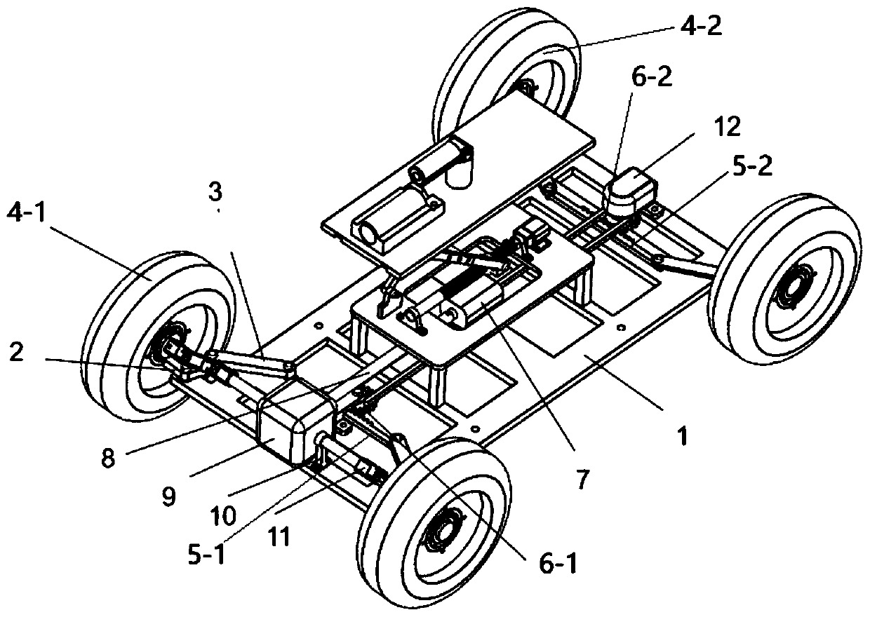
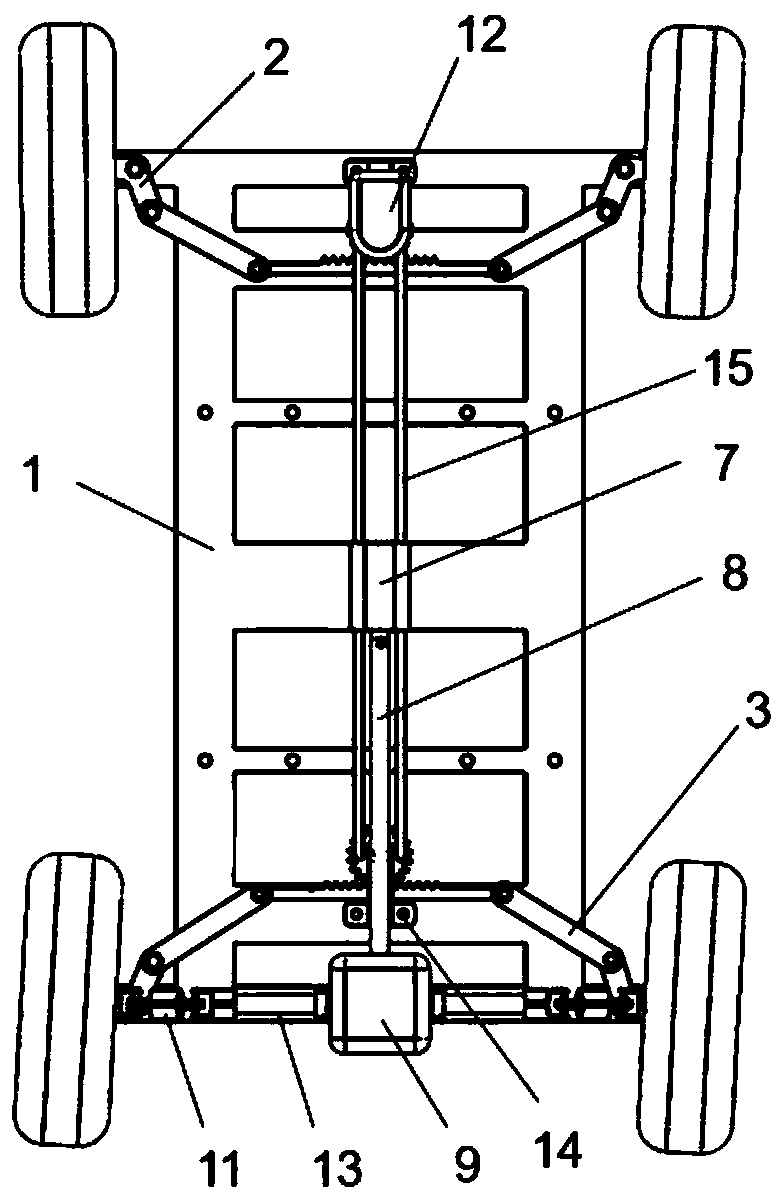
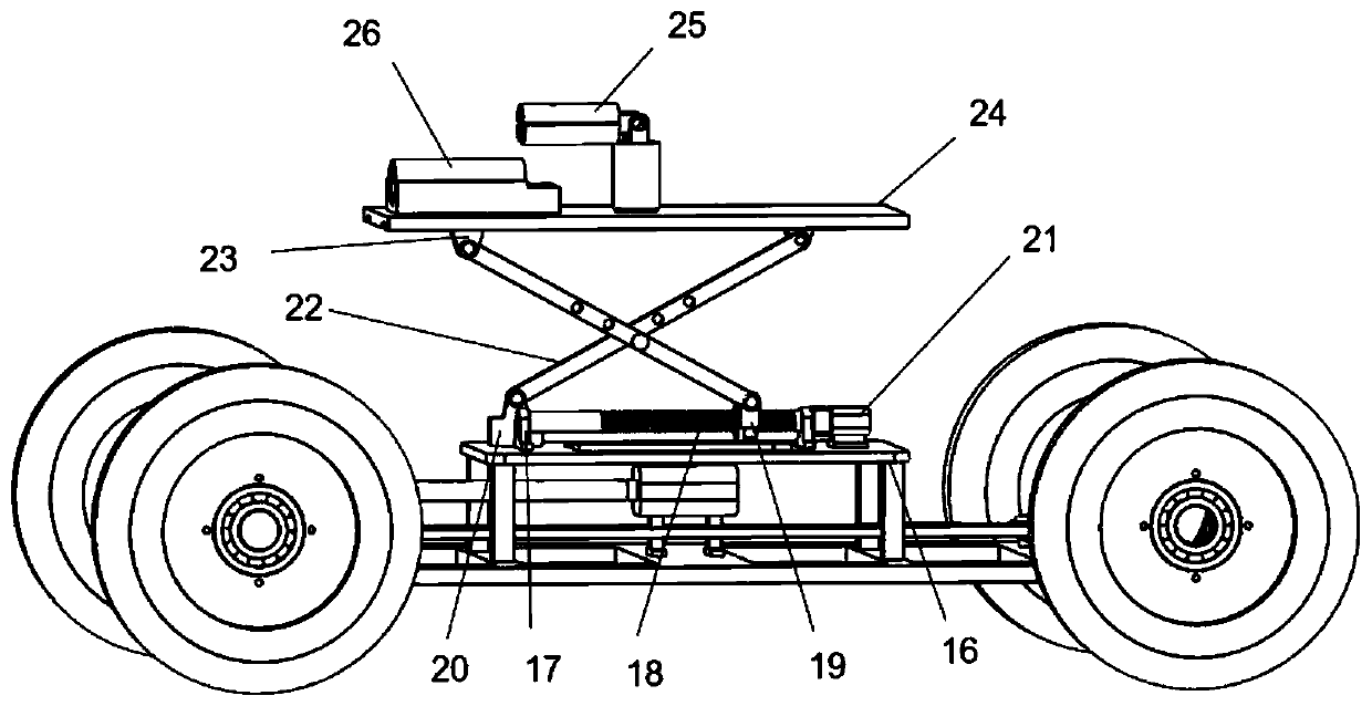
[0020] Such as Figure 1-3 Shown: a pipeline inspection robot, including a motion mechanism and a detection mechanism; the motion mechanism includes a base plate, four combined rods, two front tires 4-1, two rear tires 4-2, a first rack 5- 1. Second rack 5-2, first gear 6-1, second gear 6-2, drive motor 7, transmission shaft 8, differential 9, differential support frame 10, two universal joints 11 , steering gear 12, two axle shafts 13, two gear support frames 14 and two gear connecting rods 15; the two front tires 4-1 are symmetrically arranged on both sides of the front end of the base plate 1; the two rear tires 4 -2 is symmetrically arranged on both sides of the rear end of the bottom plat...


PUM


Abstract

The invention discloses a pipeline detection robot. The pipeline detection robot comprises a movement mechanism and a detection mechanism, wherein the mechanism mainly comprises a bottom plate, four combined rods, two front tires, two rear tires, a first rack, a second rack, a first gear, a second gear, a driving motor, a transmission shaft, a differential mechanism, a differential mechanism supporting frame, two universal joints, a steering engine, two half shafts, two gear supporting frames, two gear connecting rods, a partition plate, a telescopic mechanism, a platform, a detection probe and an illuminating lamp. Advancing and turning actions are completed through the motor and the steering engine, the detection probe is adjusted to the proper height through a lead screw nut, and an ultrasonic sensor is used for detecting the wall thickness of the pipeline to judge the corrosion degree, thereby determining whether the pipeline needs to be replaced or not.

Description

technical field [0001] The invention relates to a pipeline detection robot, which belongs to the technical field of pipeline monitoring. Background technique [0002] After a long period of use, the drainage pipes in domestic cities have begun to have problems such as aging and corrosion. If inspection and maintenance are carried out with excavated pipelines, it will seriously affect the normal life of urban residents. If the method of excavation is not adopted, the pipeline detection technology is usually used. Due to the long-term disrepair of the pipeline, the existing pipeline detection robots face the harsh and complicated pipeline environment, and some cannot pass through some obstacles smoothly. When the pipeline is small, the robot cannot run smoothly, and even some larger robots face big problems when turning. Contents of the invention [0003] The purpose of the present invention is to provide a pipeline detection robot to solve technical problems such as opera...

Claims


Application Information

Patent Timeline
Patent Type & Authority Applications(China)
IPC IPC(8): F16L55/32F16L55/40F16M11/42F16M11/38B62D7/14F16L101/30
CPCB62D7/142F16L55/32F16L55/40F16L2101/30F16M11/38F16M11/42
Inventor 马可李孟员苑明海
Owner HOHAI UNIV CHANGZHOU
Learn More