
A metal object detection system and method based on an array coil

A metal object and detection method technology, applied in the direction of radio wave measurement system, geophysical measurement, measurement device, etc., can solve the problems of complex circuit implementation, false positives, false negatives, and high requirements for de-interference, so as to improve the recognition accuracy, The effect of improving judgment accuracy

Active Publication Date: 2021-08-10
SHANDONG UNIV
View PDF0 Cites 0 Cited by
  • Summary
  • Abstract
  • Description
  • Claims
  • Application Information

AI Technical Summary

Problems solved by technology

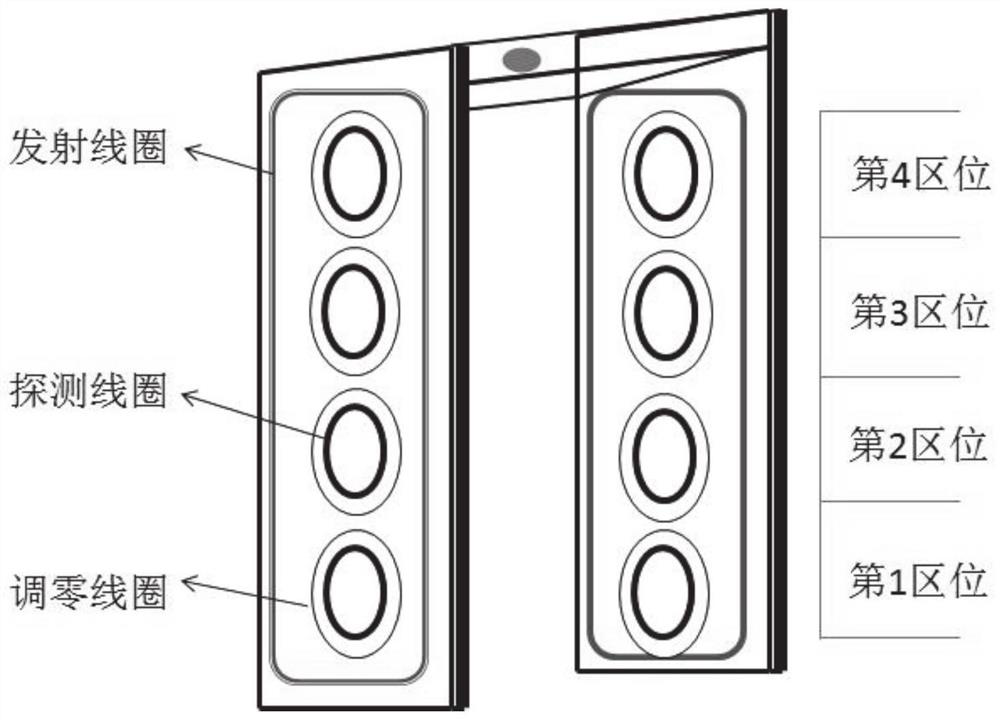
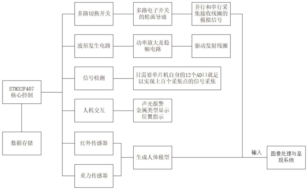
[0004] The inventors of the present disclosure have found that the traditional multi-position balance coil needs to be specially set up with a zero adjustment coil to correct the working state, such as figure 1 As shown, it can only give an alarm within a certain range during detection, and it is impossible to locate and identify metal objects, which may easily cause false alarms and missed alarms; in the signal processing part, traditional security doors use peak detection and ADC analog-to-digital conversion circuits. The ADC analog-to-digital conversion chip has high requirements for power supply and interference removal of the entire chip, and the circuit implementation is more complicated.

Method used


Image

  • A metal object detection system and method based on an array coil
  • A metal object detection system and method based on an array coil
  • A metal object detection system and method based on an array coil

Examples


Embodiment 1

[0050] Such as figure 2 and image 3 As shown, Embodiment 1 of the present disclosure provides a metal object detection system based on an arrayed coil, including at least two oppositely arranged detection panels, and each detection panel is covered with an array of balanced coils;

[0051] Under the action of the exciting magnetic field, according to the variation of the induced voltage of each balance coil on the detection panel, it is judged whether there is a metal object and the shape and position of the metal object.

[0052] The array-type balance coils are specifically arranging a plurality of balance coils sequentially on the entire detection panel in a matrix manner.

[0053] In other implementation manners, the detection panel may also be pre-divided into a plurality of square or rectangular areas in a matrix, and then a balance coil is arranged in each area along the edge of the area.

[0054] Of course, the division method here may also be other shapes, such as...

Embodiment 2

[0064] Embodiment 2 of the present disclosure provides an array coil-based metal object detection method, using the array coil-based metal object detection system described in Embodiment 1;

[0065] The excitation coil on the detection panel obtains the excitation current;

[0066] When no metal object enters, detect the induced voltage of each balance coil;

[0067] According to the difference between the induction voltage of each balance coil on the detection panel and the induction voltage when no metal object enters, it is judged whether there is a metal object entering;

[0068] The shape and relative position of the metal object can be judged according to the difference of the induced voltage of each balance coil.

[0069] The specific detection principle is as follows: the detection principle is: the array coil is covered with the entire detection panel, and each grid is a separate coil. Under the action of the excitation magnetic field, when there is no metal object i...


PUM


Abstract

The present disclosure provides a metal object detection system based on an arrayed coil, in the technical field of data metal object detection, including at least two opposite detection panels, each detection panel is covered with an array of balanced coils; Under the action, according to the magnitude of the change in the induced voltage of each balance coil on the detection panel, it is judged whether there is a metal object and the shape and position of the metal object; It is a separate coil. Under the action of the exciting magnetic field, when there is no metal object in the detection area, the properties of each coil output are specific values. When the metal object enters the detection area, the property of the balance coil changes, and the property change is realized. Precise identification of the shape, contour, location and type of metallic objects.

Description

technical field [0001] The present disclosure relates to the technical field of metal object detection, and in particular to a metal object detection system and method based on an array coil. Background technique [0002] The statements in this section merely provide background information related to the present disclosure and may not necessarily constitute prior art. [0003] The application of metal object detection technology in security inspection and other fields has attracted extensive attention. At present, the metal object detection method used in security inspection is mainly the multi-position coil detection method based on electromagnetic induction. [0004] The inventors of the present disclosure have found that the traditional multi-position balance coil needs to be specially set up with a zero adjustment coil to correct the working state, such as figure 1 As shown, it can only give an alarm within a certain range during detection, and cannot locate and identif...

Claims


Application Information

Patent Timeline
Patent Type & Authority Patents(China)
IPC IPC(8): G01V3/11
CPCG01V3/101
Inventor 刘志珍侯延进魏小钊田寒梅
Owner SHANDONG UNIV
Learn More