Grinding device for mechanical machining parts

A mechanical processing and grinding technology, which is applied in metal processing equipment, grinding/polishing equipment, grinding machines, etc., can solve the problem of poor surface grinding quality, poor shape tolerance, grinding accuracy that cannot meet the design requirements, and poor coordination requirements. High-level problems, to achieve the effect of improving the scope of application, improving dimensional retention and grinding surface quality

Inactive Publication Date: 2018-10-19
ZIBO VOCATIONAL INST
View PDF7 Cites 0 Cited by
  • Summary
  • Abstract
  • Description
  • Claims
  • Application Information

AI Technical Summary

Problems solved by technology

[0002] In the machining process, precision plunger sleeves are common processing parts. The surface accuracy of high-precision plunger sleeves has high requirements. At this stage, traditional grinding tools are used for grinding. The surface grinding quality and shape tolerance Poor. The traditional grinding method is generally to drill holes first, and then perform multiple internal grinding. This method requires multiple processing, and the processing accuracy is not easy to control. It is easy to cause the grinding accuracy to fail to meet the design requirements

Method used


Image

  • Grinding device for mechanical machining parts
  • Grinding device for mechanical machining parts
  • Grinding device for mechanical machining parts

Examples


Embodiment 1

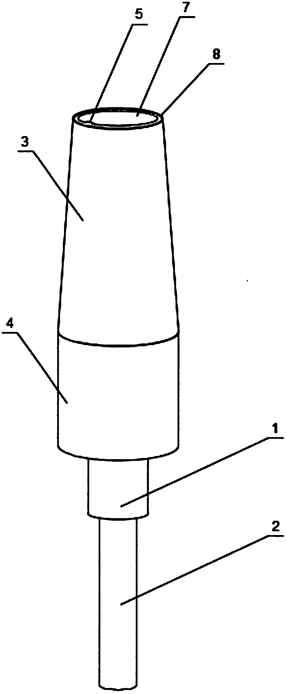
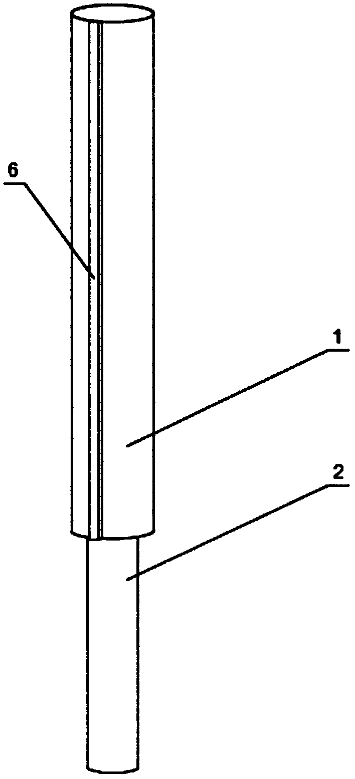
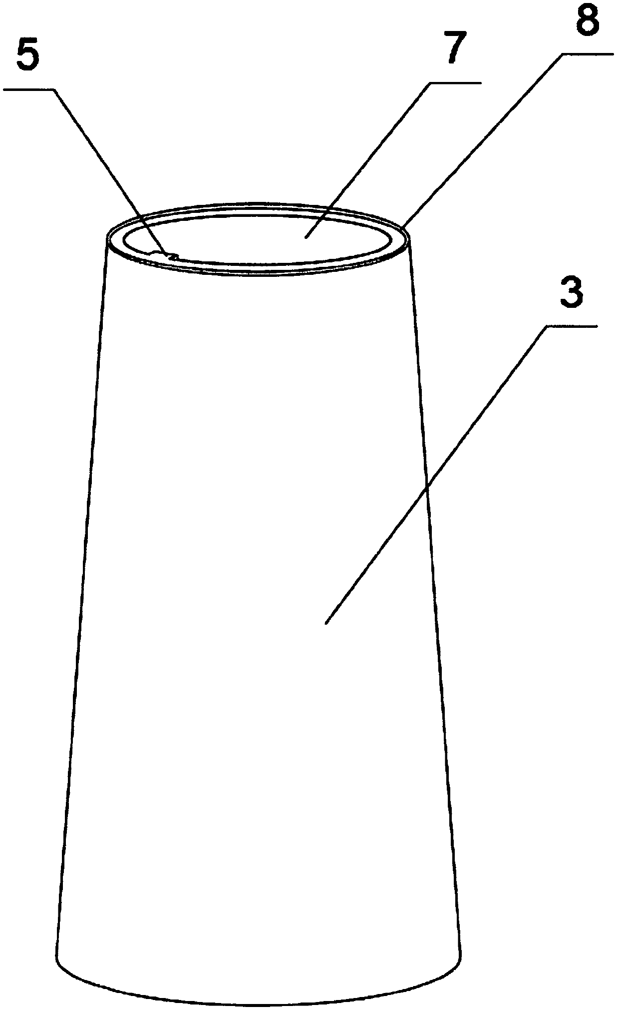
[0023] Such as figure 1 , figure 2 , image 3 with Figure 4 As shown, a machined workpiece grinding device includes a tool bar 1 and a tool handle 2 connected to a machine tool. A grinding sleeve is provided on the tool bar 1. The grinding cover includes a conical grinding cover 3 and a cylindrical grinding Set 4, the conical grinding set 3 and the cylindrical grinding set 4 are coaxially arranged, the conical grinding set 3 and the cylindrical grinding set 4 are tightly connected, the conical grinding set 3 and the cylindrical grinding set The inner sides of 4 are provided with connecting key 5, and the knife bar 1 is provided with the key groove 6 that cooperates with connecting key 5. The middle part of the conical grinding sleeve 3 is a cylindrical through hole 7 with the same diameter as the cutter bar 1 . The outer sides of the conical grinding sleeve 3 and the cylindrical grinding sleeve 4 are provided with a grinding layer 8, and the grinding layer 8 is connected...

Embodiment 2

[0025] Such as Figure 5 As shown, the difference between this embodiment and the above embodiments is that the conical grinding sleeve 3 includes a plurality of sub-grinding sleeves 301 , and the sub-grinding sleeves 301 are sequentially connected to form a conical grinding sleeve 3 .

[0026] When in use, the tool handle 2 is connected with the machine tool, and the tool handle 2 drives the conical grinding sleeve 3 and the cylindrical grinding sleeve 4 to rotate, passing through the two grinding areas on the conical grinding sleeve 3 and the cylindrical grinding sleeve 4 Grinding the plunger sleeve, the outer surface of the cylindrical grinding sleeve 4 and the conical grinding sleeve 3 are closely connected, the workpiece is first ground through the conical grinding sleeve 3, and then through the cylindrical grinding sleeve 4 Carry out precision grinding, through two combined grinding methods, the shape and surface quality of the plunger bushing can meet high-quality requi...


PUM


Abstract

The invention discloses a grinding device for mechanical machining parts. The device includes a knife bar and a knife handle connected to a machine tool; the knife is provided with a grinding sleeve;the grinding sleeve includes a taper grinding sleeve and a cylindrical grinding sleeve; the taper grinding sleeve is tightly connected to the cylindrical grinding sleeve; the outer sides of the tapergrinding sleeve and the cylindrical grinding sleeve are provided with grinding layers; the surface of the taper grinding sleeve is a CBN grinding layer; and the surface of the cylindrical grinding sleeve is a diamond micro powder abrasive grinding layer. A grinding process can be performed on a plunger sleeve through two grinding areas which are the taper grinding sleeve and the cylindrical grinding sleeve; the outer surface of the cylindrical grinding sleeve is tightly connected to the outer surface of the taper grinding sleeve; a workpiece can first be ground by the taper grinding sleeve, and then be precisely ground by the cylindrical grinding sleeve; and through a combination of the two grinding modes, the shape and surface quality of a plunger sleeve hole can meet high quality requirements.

Description

technical field [0001] The invention relates to the technical field of machining, in particular to a grinding device for machined parts. Background technique [0002] In the machining process, precision plunger sleeves are common processing parts. The surface accuracy of high-precision plunger sleeves has high requirements. At this stage, traditional grinding tools are used for grinding. The surface grinding quality and shape tolerance Poor, the traditional grinding method is generally to drill holes first, and then perform multiple internal grinding. This method requires multiple processing, and the processing accuracy is not easy to control. It is easy to cause the grinding accuracy to fail to meet the design requirements. Contents of the invention [0003] In order to overcome the above technical problems, the object of the present invention is to provide a grinding device for machined parts. [0004] According to the purpose of the present invention, the following te...

Claims


Application Information

Patent Timeline
Patent Type & Authority Applications(China)
IPC IPC(8): B24B27/00
CPCB24B27/0076
Inventor 杨莉莉
Owner ZIBO VOCATIONAL INST
Why Eureka
Try Eureka