
Steam heating type cooking utensil

A cooking utensil and heating technology, applied in the field of kitchen appliances, can solve the problems of high temperature, heavy and unsightly body, sticking to the pot, etc.

Active Publication Date: 2020-08-28
JOYOUNG CO LTD
View PDF9 Cites 1 Cited by
  • Summary
  • Abstract
  • Description
  • Claims
  • Application Information

AI Technical Summary

Problems solved by technology

Known household electric rice cookers mainly have two heating methods: one is to heat the inner pot through a heating plate or an electromagnetic wire plate, which is prone to problems such as local high temperature and sticky pot, and cannot realize real three-dimensional heating; The second is steam heating. In contrast, steam heating has better heating uniformity and can solve the problems existing in traditional electric heating. Therefore, steam heating has gradually attracted the attention of the industry in recent years.
[0003]A steam rice cooker disclosed in the prior art, in terms of product structure, subverts the structural design of the traditional rice cooker built-in pot, and adopts an external pot structure. The body as a heating platform forms an open space, and the pot for placing food can be placed in the open space. The pot is located outside the body and supported by the platform at the bottom of the body. The machine head is introduced into the pot for heating, and the machine head presses the pot tightly to prevent the pot from moving and affecting the stable output of steam. This involves the problem of the user taking and placing the pot after cooking. It is required that the machine head can be in contact with the pot after cooking. The utensils are separated and a certain space is formed to facilitate the user to take and place the pot. Although the above-mentioned purpose can be achieved by using the telescopic machine head, the telescopic machine head requires a large installation space for the body, resulting in a thick and unsightly body. The space provided by the retractable head is relatively small, and the experience of picking and placing pots is not good.

Method used


Image

  • Steam heating type cooking utensil
  • Steam heating type cooking utensil
  • Steam heating type cooking utensil

Examples


Embodiment 1

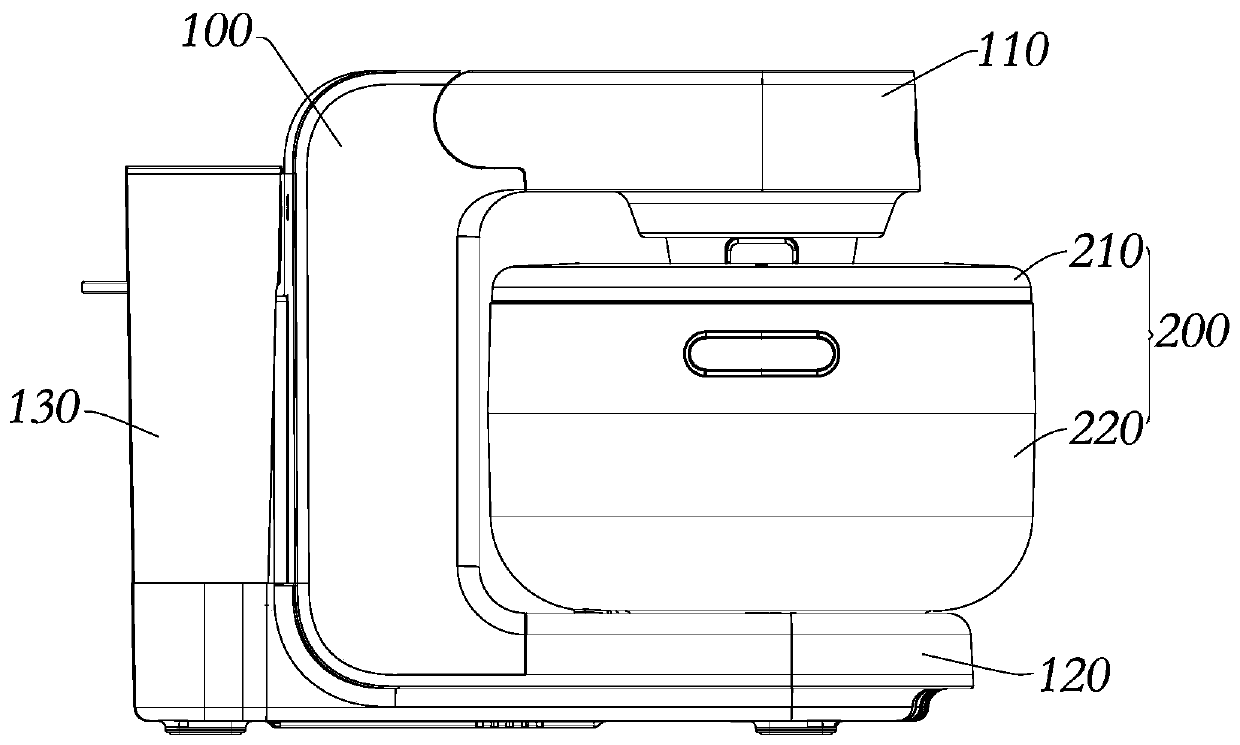
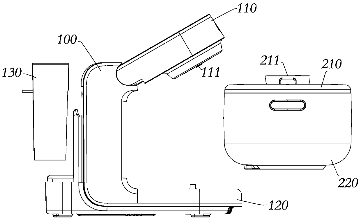
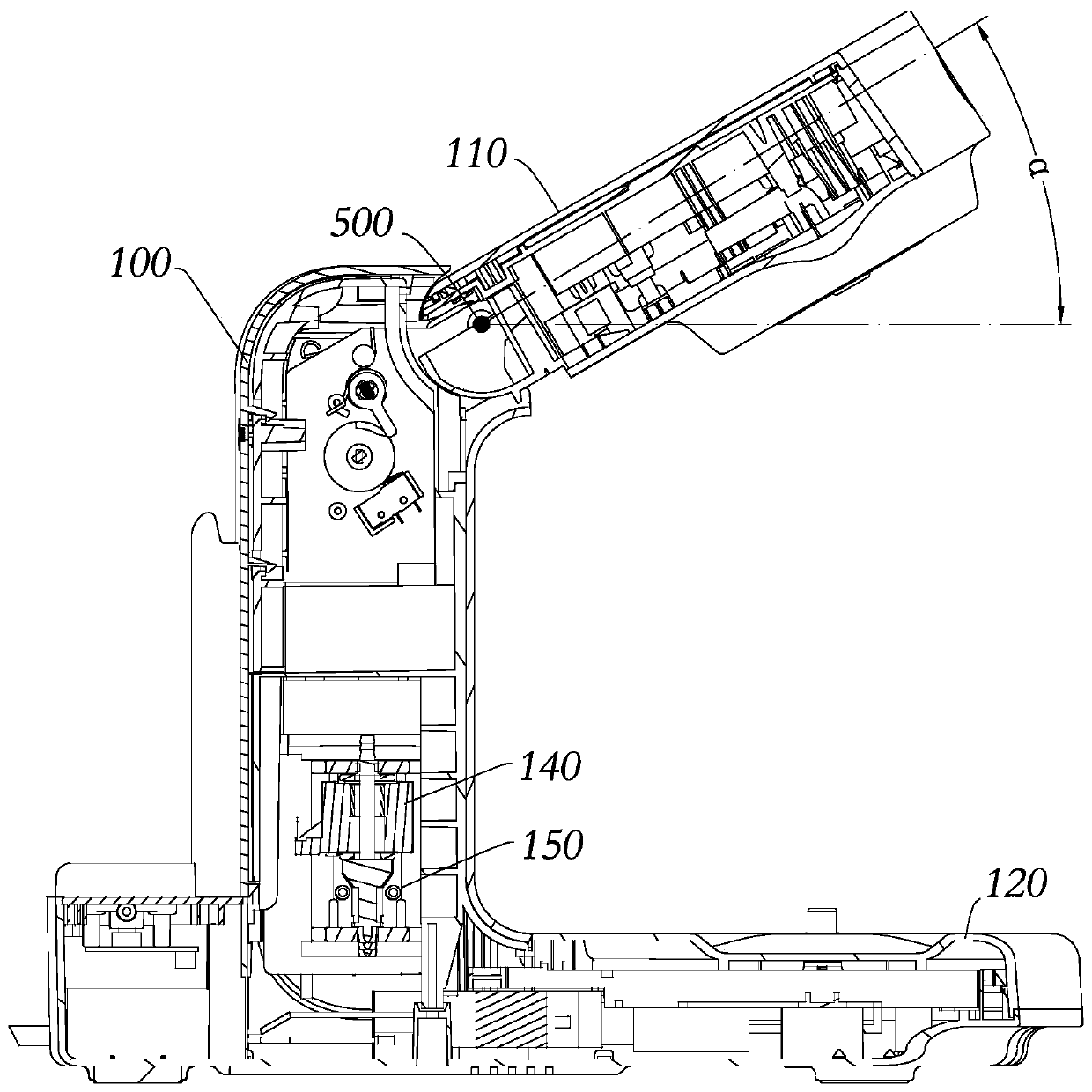
[0058] refer to Figure 1-3 , the steam heating cooking utensil proposed in Embodiment 1 of the present invention includes a body 100 and a pot 200, a machine head 110 is arranged on the upper part of the body 100, a bearing platform 120 is arranged on the lower part of the body 100, and the cooking utensil 200 is placed on the bearing platform 120. An open space for accommodating the pot 200 is formed between the head 110 and the carrying platform 120, and the machine head 110 and the body 100 are connected by a rotation limiting device, which limits the machine head 110 to the first position where the pot 200 is docked. And switch between the second station separated from the pot 200.

[0059] Specifically: the body 100 of this embodiment is provided with a steam generator 150 (such as: a water storage boiler, an instant boiler, etc.) and a water pump 140, and a water tank 130 is set on one side of the body 100, and the water pump 140 works to pump the water in the water tan...

Embodiment approach

[0066] combine Figure 4 , 5 The rotation limiting device includes a limiting plate 300 installed on the machine head 110 and a fixed bracket 400 installed on the body 100. The fixed bracket 400 is provided with a limiting shaft 410, and the limiting plate 300 is provided with a limiting hole 310. The positioning hole 310 has a first limiting end and a second limiting end. When the limiting shaft 410 moves to the first limiting end, it defines the first station and can be locked at the first limiting end. The limiting shaft 410 moves to The second limit end defines the second station. Specifically: the machine head 110 includes a machine head upper cover 112 and a machine head lower cover 113, one end of the stop plate 300 is fixedly installed on the machine head lower cover 113, and the other end of the stop plate 300 is provided with an arc-shaped stop hole 310, The limit hole 310 includes a guide segment 312 of equal width and a limit segment 311 wider than the guide segm...

Embodiment 2

[0080] refer to Figure 10 , 11 , different from Embodiment 1, the solution of this embodiment changes the locking and unlocking methods of the limit shaft 410, specifically:

[0081] The rotation limiting device includes a limiting plate 300 and a fixed bracket 400. One end of the limiting plate 300 is fixedly mounted on the lower cover 113 of the machine head, and the other end of the limiting plate 300 is provided with a limiting hole 310. The limiting hole 310 includes a vertical section 314 And the horizontal section 313 extending horizontally from the bottom of the vertical section 314, the upper end of the vertical section 314 is the second limiting end, and the horizontal section 313 forms the first limiting end. The rotating shaft 500 is fixed on the limiting plate 300 through integral injection molding or other methods, and the two ends of the rotating shaft 500 are rotatably limited on the lower cover 113 of the machine head. One end of the limiting shaft 410 is i...


PUM


Abstract

The invention discloses a steam heating type cooking utensil and belongs to the field of kitchen appliances. The problem that cookware in an existing steam heating type cooking utensil is inconvenientto take and place is solved. The steam heating type cooking utensil comprises a machine body and a pot, a machine head is arranged on the upper part of the machine body, a bearing table is arranged on the lower portion of the machine body, a pot is placed on the bearing table, an open space for accommodating the cookware is formed between the machine head and the bearing table, the machine head is connected with the machine body through a rotary limiting device, the rotary limiting device limits the machine head to be overturned and switched between a first station in butt joint with the cookware and a second station separated from the cookware, and a driving piece is arranged on the rotary limiting device and used for driving the machine head to turn over upwards from the first station to the second station and allowing the machine head to turn over manually from the second station to the first station. The opening and closing mode of the machine head is optimized, the larger takingand placing space and taking and placing freedom degree are provided for cookware, and the taking and placing experience of the cookware is improved.

Description

【Technical field】 [0001] The invention relates to the field of kitchen appliances, in particular to a steam heating cooking appliance. 【Background technique】 [0002] As one of the most commonly used kitchen cooking utensils at present, the electric rice cooker can be used not only for cooking, but also for cooking porridge and soup to meet the needs of people's fast-paced work and life. Known household electric rice cookers mainly have two heating methods: one is to heat the inner pot through a heating plate or an electromagnetic wire plate, which is prone to problems such as local high temperature and sticky pot, and cannot realize real three-dimensional heating; The second is steam heating. In contrast, steam heating has better heating uniformity and can solve the problems of traditional electric heating. Therefore, steam heating has gradually attracted the attention of the industry in recent years. [0003] A steam rice cooker disclosed in the prior art, in terms of pro...

Claims


Application Information

Patent Timeline
Patent Type & Authority Applications(China)
IPC IPC(8): A47J27/04A47J27/00A47J36/00
CPCA47J27/04A47J27/002A47J36/00
Inventor 朱泽春吕卫卫于文强蒋志成
Owner JOYOUNG CO LTD
Learn More