Graphite isolation device for float glass forming process

A forming process and float glass technology, applied in the field of graphite isolation devices for float glass forming process, can solve problems such as irreparable, difficult operation, heavy workload, etc., and achieve good use effect, flexible operation, and rapid replacement Effect

Pending Publication Date: 2020-08-28
BENGBU CHINA OPTOELECTRONIC TECH CO LTD
View PDF6 Cites 0 Cited by
  • Summary
  • Abstract
  • Description
  • Claims
  • Application Information

AI Technical Summary

Problems solved by technology

[0005] 1. The graphite strip is installed in a cold state. Due to the large difference in expansion coefficient between graphite and screw, steel is about 12E-6 / k and graphite is about 220E-6 / k. When the temperature rises to high temperature, the screw will loosen and the fixation will not be firm.
[0006] 2. When forming the leader or when there is an abnormality, it is usually necessary to open the side seal of the tin tank, and use tools such as hooks and shovels to manually operate the glass plate. The tools such as hooks will press the graphite strip, and it is easy to press the graphite strip off.
[0007] 3. If graphite is used for a long time at high temperature, it will burn slowly, which will cause the screw hole to become larger and cause the screw to loosen
[0008] 4. When the graphite strip falls off for some reason and needs to be replaced, since the steel pressure plate is welded to the steel structure of the tank shell, the steel pressure plate needs to be cut off, and after replacing the new graphite strip, it is necessary to keep the working condition down and weld Restoration, heavy workload, difficult operation, harsh working environment
Once the graphite strip is burned, it cannot be repaired
[0010] 6. Installed in a cold state, it is easy to loosen and fall off after heating up
After a long time of use, it may also become loose and fall off due to burning

Method used


Image

  • Graphite isolation device for float glass forming process
  • Graphite isolation device for float glass forming process
  • Graphite isolation device for float glass forming process

Examples


Embodiment Construction

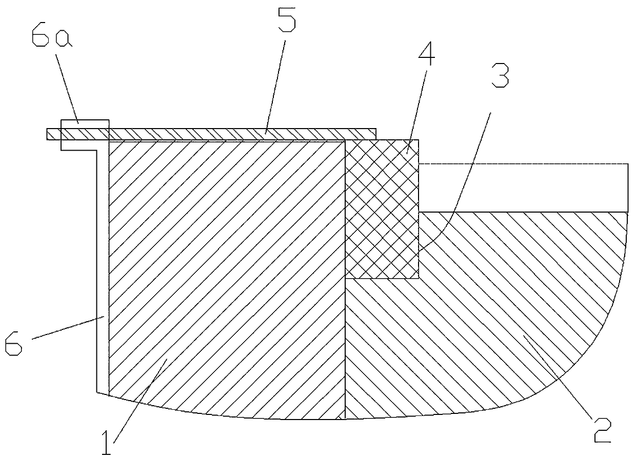
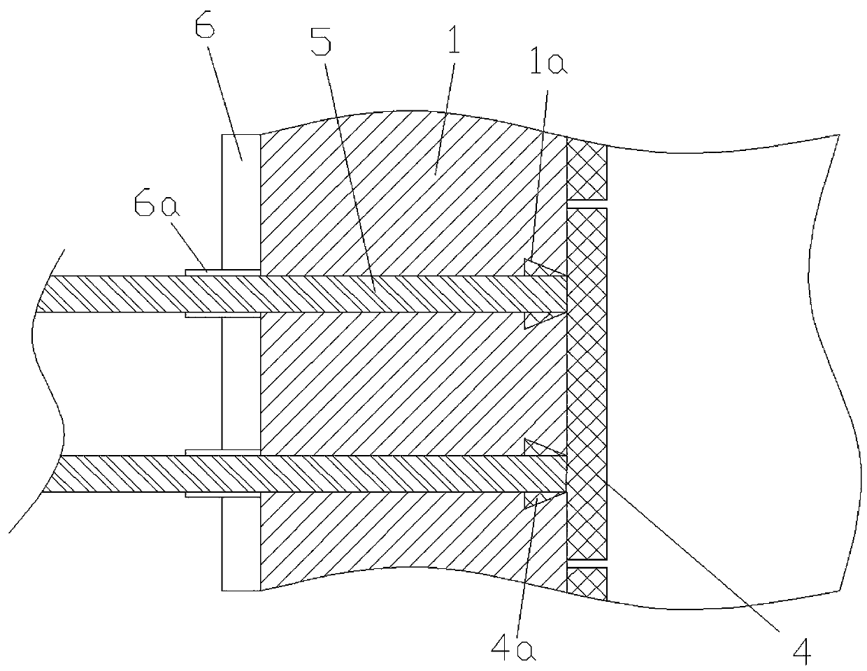
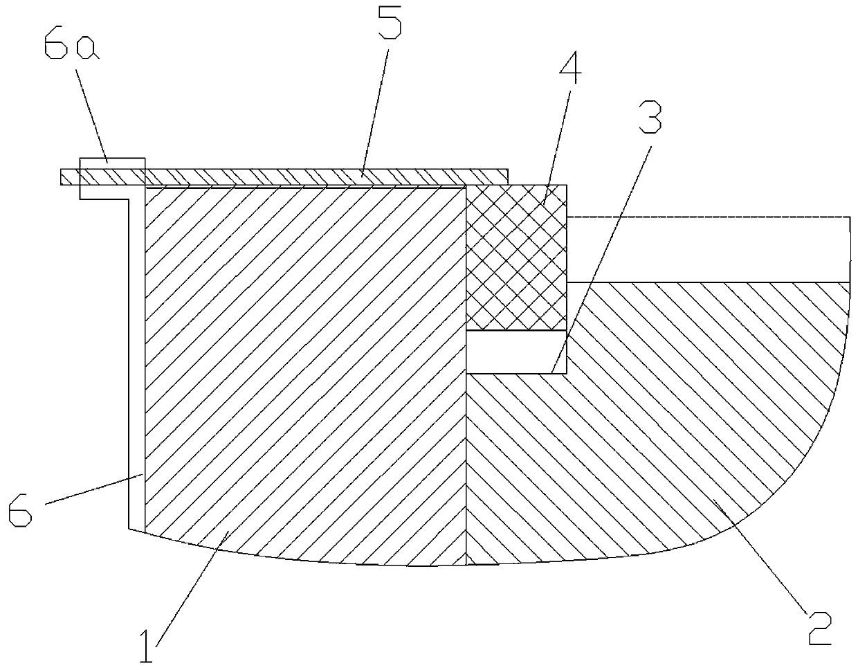
[0021] Such as Figure 1-3 As shown, a graphite isolation device for float glass molding process, it includes a tin bath side wall brick 1 and a tin bath bottom brick 2, on the tin bath bottom brick 2 close to the tin bath side wall brick 1 is provided with a Slot 3. On the groove side wall brick 1 on one side of the installation groove 3, there are longitudinally distributed chute 1a, and the chute 1a is a dovetail groove.

[0022] Installing groove 3 is provided with graphite liner 4, is provided with along the graphite liner 4 vertically distributed slide block 4a on graphite liner 4 near the graphite liner 4 side wall of tin tank side wall brick 1 side, described The slider 4a is inserted into the chute 1a to form a sliding fit therewith. The slider 4a and the graphite lining 4 are integrally structured.

[0023] An outer wall 6 is arranged on the outside of the side wall brick 1 of the tin bath, and an insert ring 6a is fixed on the top of the outer wall 6. The central...


PUM


Abstract

The invention provides a graphite isolation device for a float glass forming process. The device comprises a molten tin bath side wall brick (1) and a molten tin bath bottom brick (2), wherein a mounting groove (3) is formed in the molten tin bath bottom brick (2) close to the molten tin bath side wall brick (1); a graphite lining (4) is arranged in the mounting groove (3). The device is characterized in that a sliding groove (1a) is formed in the molten tin bath side wall brick (1), a sliding block (4a) clamped into the sliding groove (1a) is arranged on one side of the graphite lining (4), an outer wall (6) is arranged on the outer side of the molten tin bath side wall brick (1), an inserting ring (6a) is arranged on the outer wall (6), and a pressing rod (5) correspondingly matched withthe graphite lining (4) is arranged in the inserting ring (6a). The device has the advantages of simple structure, flexibility in operation, quickness in replacement of the graphite lining, better use effect and the like.

Description

Technical field: [0001] The invention relates to the field of float glass production, in particular to a graphite isolation device for a float glass forming process. Background technique: [0002] The float method is a method in which the molten glass in the melting furnace flows into the tin bath to form flat glass on the surface of the molten metal tin liquid. The tin bath is the key thermal equipment for float glass forming. The tin bath is filled with tin liquid. The molten glass floats on the surface of the liquid, and under the control of a suitable temperature gradient, it is gradually shaped by the edge pulling machine to produce flat glass with the required thickness and width. After the glass plate is shaped, the glass plate needs to be led out to the transition roller at the end of the tin bath, and sent to the annealing furnace continuously. [0003] The body of the tin bath is a closed device composed of refractory materials and steel plates. Since the glass li...

Claims


Application Information

Patent Timeline
Patent Type & Authority Applications(China)
IPC IPC(8): C03B18/16
CPCC03B18/16
Inventor 王保平侯建伟吴星达
Owner BENGBU CHINA OPTOELECTRONIC TECH CO LTD
Why Eureka
Try Eureka