Gas turbine lubricating oil filter
A technology for lubricating oil and gas turbine, which is applied in the direction of engine lubrication, turbine/propulsion lubrication, mechanical equipment, etc. High reliability, low manufacturing cost, convenient and quick installation
- Summary
- Abstract
- Description
- Claims
- Application Information
AI Technical Summary
Problems solved by technology
Method used
Image

Examples
specific Embodiment approach 1
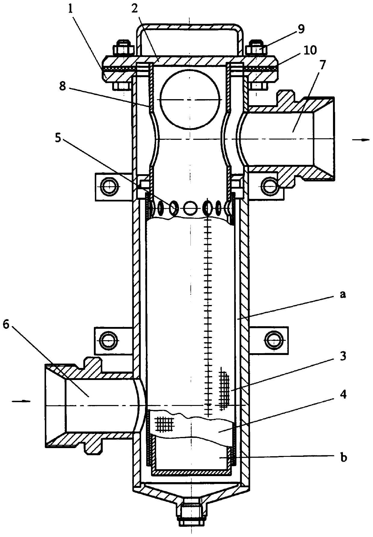
[0013] Specific implementation mode one: combine figure 1 This embodiment is described. The gas turbine lubricating oil filter in this embodiment includes a filter housing 1 and a filter mechanism. The housing 1 is provided with a first chamber a, and the filter mechanism is arranged in the first chamber a. The filter housing The lower part of the body 1 is provided with an inlet 6, and the upper part of the filter housing 1 is provided with an outlet 7.
[0014] This embodiment can roughly purify the lubricating oil, effectively intercept larger impurities formed due to the damage of the fine filter element, and can conduct a short-term test on the gas turbine without a fine lubricating oil filter.
specific Embodiment approach 2
[0015] Specific implementation mode two: combination figure 1 This embodiment is described. The filter mechanism of the gas turbine lubricating oil filter in this embodiment includes a skeleton 8 and a filter screen assembly. The skeleton 8 is inserted in the first chamber a, and the second chamber b is arranged in the skeleton 8. The skeleton 8 A plurality of holes 5 are arranged on the upper part of the frame 8, and the oil outlet at the upper end of the frame 8 communicates with the outlet 7, and the filter screen assembly is sleeved on the frame 8. Other components and connections are the same as those in the first embodiment.
specific Embodiment approach 3
[0016] Specific implementation mode three: combination figure 1 Describe this embodiment, the filter screen assembly of the gas turbine lubricating oil filter in this embodiment includes a first filter screen 3 and a second filter screen 4, and the first filter screen 3 and the second filter screen 4 are sequentially set on the skeleton from outside to inside 8, and the upper edges of the first filter screen 3 and the second filter screen 4 are located between the hole 5 and the oil outlet at the upper end of the frame 8. Other components and connections are the same as those in the second embodiment.
PUM
 Abstract
Description
Claims
Application Information
 - R&D
- Intellectual Property
- Life Sciences
- Materials
- Tech Scout
- Unparalleled Data Quality
- Higher Quality Content
- 60% Fewer Hallucinations
Browse by: Latest US Patents, China's latest patents, Technical Efficacy Thesaurus, Application Domain, Technology Topic, Popular Technical Reports.
© 2025 PatSnap. All rights reserved.Legal|Privacy policy|Modern Slavery Act Transparency Statement|Sitemap|About US| Contact US: help@patsnap.com