Low-voltage wire section measuring instrument
A technology of wire cross section and measuring instrument, applied in the direction of mechanical diameter measurement, etc., can solve the problems of difficult and accurate measurement, inability to distinguish, low measurement accuracy, etc., to achieve the effect of improving efficiency, simple and intuitive measurement, and high measurement accuracy
- Summary
- Abstract
- Description
- Claims
- Application Information
AI Technical Summary
Problems solved by technology
Method used
Image
Examples
Embodiment 1
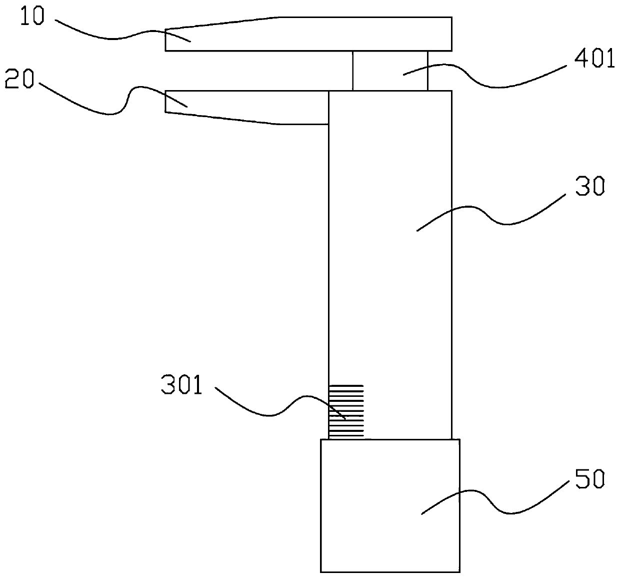
[0029] like Figure 4 As shown, a low-voltage wire section measuring instrument includes an upper clip 10, a lower clip 20, a main body 30 and a driving rod, wherein, in this embodiment, the main body 30 is a cylindrical structure, and a cavity is provided in the main body 30 Two ends of the main body 30 are provided with openings communicating with the cavity, and the lower clip 20 is fixedly connected to the outer wall of the upper end of the main body 30 . The driving rod includes a first rod body 401 and a sleeve body 50. The first rod body 401 is movably arranged in the cavity. The upper end of the first rod body 401 passes through the upper end opening of the main body 30 and is connected with the upper clip 10. The lower end of the body 30 passes through the opening and is connected with the sleeve body 50 , which is movably sleeved on the outer wall of the main body 30 .
[0030]Wherein, in this embodiment, the driving rod is movably connected with the main body 30 th...
Embodiment 2
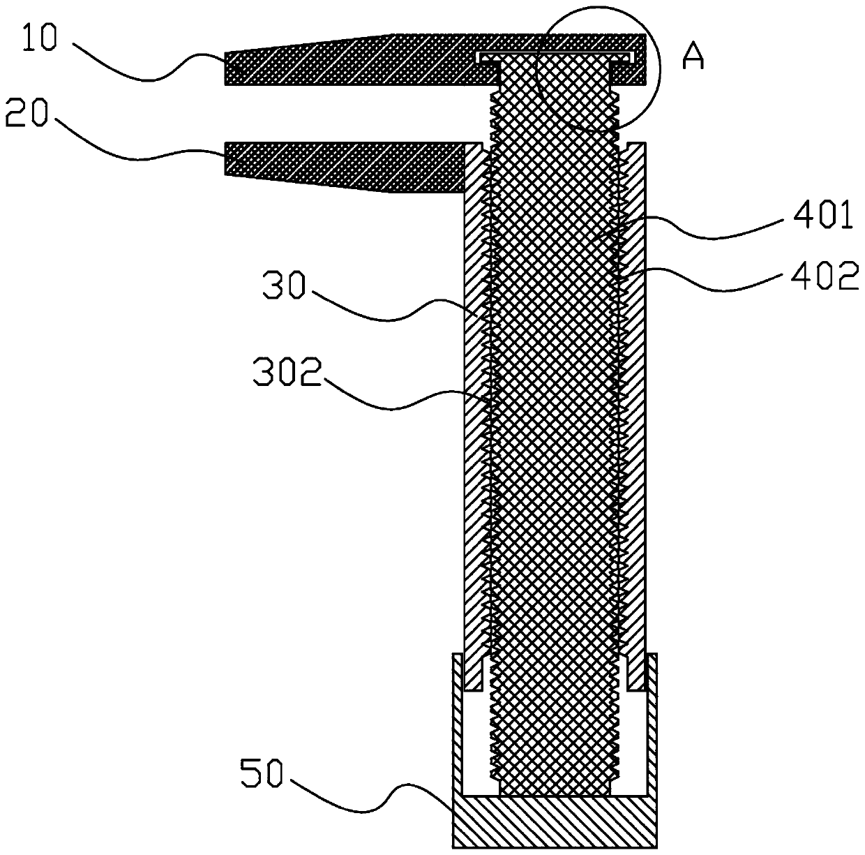
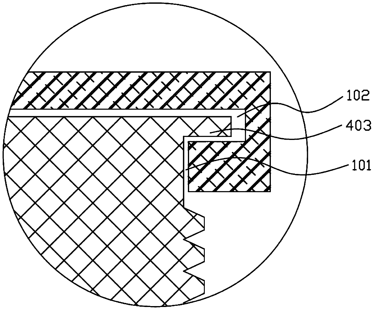
[0036] like figure 1 , 2 As shown, this embodiment is similar to Embodiment 1, the difference is that in this embodiment, the thread pair includes a third threaded part 302 and a fourth threaded part 402, and the third threaded part 302 is a threaded part arranged on the inner wall of the cavity. The internal thread, the fourth threaded part 402 is an external thread provided on the outer wall of the first rod body 401, and the third threaded part 302 and the fourth threaded part 402 cooperate with each other. Due to the action of the third threaded portion 302 and the fourth threaded portion 402 , by rotating the first rod 401 , the first rod 401 can move upward or downward to drive the action of the upper clip 10 .
Embodiment 3
[0038] like Figure 5 As shown, this embodiment is similar to Embodiment 1 or 2, the difference is that, in this embodiment, the driving rod includes a second rod body 601, a nut 602 is connected to the outside of the main body 30, the second rod body 601 is a threaded rod, and the screw thread The rod cooperates with the nut 602 , an indicating block 603 is arranged on the threaded rod, and the end of the threaded rod is connected with the upper clip 10 . Due to the action of the third threaded portion 302 and the fourth threaded portion 402 , by rotating the first rod 401 , the first rod 401 can move upward or downward to drive the action of the upper clip 10 .
[0039] Further, a handle 604 is also included, and the handle 604 is connected with the end of the second rod body 601 . The handle 604 can increase the holding area, which is convenient for the staff to rotate the second rod body 601 .
PUM
 Abstract
Description
Claims
Application Information
 - R&D
- Intellectual Property
- Life Sciences
- Materials
- Tech Scout
- Unparalleled Data Quality
- Higher Quality Content
- 60% Fewer Hallucinations
Browse by: Latest US Patents, China's latest patents, Technical Efficacy Thesaurus, Application Domain, Technology Topic, Popular Technical Reports.
© 2025 PatSnap. All rights reserved.Legal|Privacy policy|Modern Slavery Act Transparency Statement|Sitemap|About US| Contact US: help@patsnap.com


