

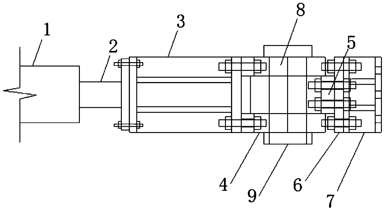
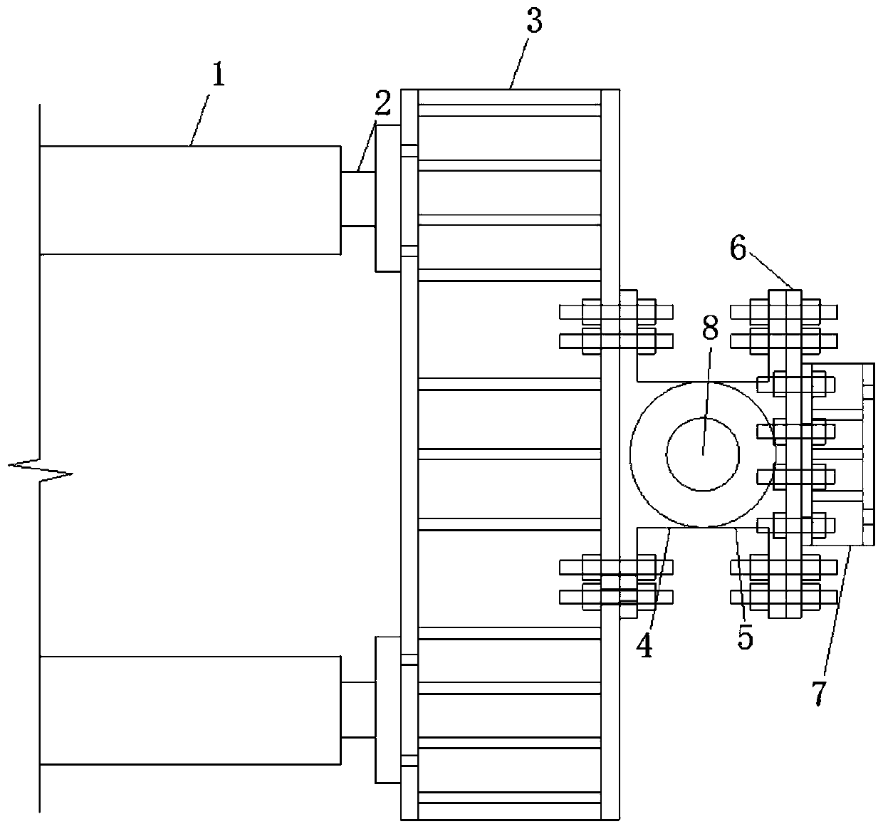
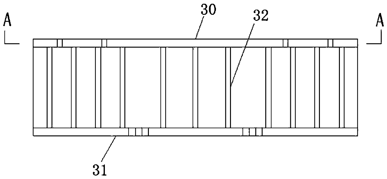
Test piece loading test device
A loading test device and technology of loading device, which are applied in measurement devices, testing of mechanical components, testing of machine/structural components, etc., can solve the problems of obvious torsional effect, high ultimate bearing capacity, and aggravated torsional effect, and eliminate the problems of torsional effect. Torsional effect, effect of reducing torsional eccentricity
- Summary
- Abstract
- Description
- Claims
- Application Information
AI Technical Summary
Problems solved by technology
Method used
Image

Examples
Embodiment Construction
[0030] For a better understanding of the present invention, the following examples are further descriptions of the present invention, but the content of the present invention is not limited to the following examples.
[0031] It should be noted that the experimental methods described in the following embodiments, unless otherwise specified, are conventional methods, and the reagents and materials, if not otherwise specified, can be obtained from commercial sources; in the description of the present invention, The terms "landscape", "portrait", "top", "bottom", "front", "rear", "left", "right", "vertical", "horizontal", "top", "bottom", The orientation or positional relationship indicated by "inner", "outer", etc. is based on the orientation or positional relationship shown in the drawings, which is only for the convenience of describing the present invention and simplifying the description, and does not indicate or imply that the referred device or element must have Certain or...
PUM
 Abstract
Description
Claims
Application Information