Quick cable mounting device

A kind of cable device and fast technology, applied in the direction of cable suspension device, electrical components, etc., can solve the problems affecting the service life of the cable, hidden dangers, wiring entanglement, etc., to achieve good environmental adaptation effect, prolong service life, improve stability sexual effect

Active Publication Date: 2020-08-28
张于峰 +1
View PDF7 Cites 11 Cited by
  • Summary
  • Abstract
  • Description
  • Claims
  • Application Information

AI Technical Summary

Problems solved by technology

However, the existing method used in most places is to wrap the household wiring on the main line. This method will bring a lot of work to maintenance and emergency repair personnel, and there is a relatively large potential safety hazard.
[0003] The existing cable installation bracket has a traditional structure, which is inconvenient for quick installation and fixing of the cable, and cannot provide reliable elastic support for the cable. The environmental adaptation effect is poor, which increases the wear and tear of the cable and affects the service life of the cable.

Method used


Image

  • Quick cable mounting device
  • Quick cable mounting device
  • Quick cable mounting device

Examples


Embodiment 1

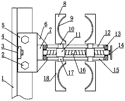
[0017] see Figure 1-3 , in the embodiment of the present invention, a quick installation cable device includes a device body 13, one end of the device body 13 is fixed with an elastic limit assembly 7, and the elastic limit assembly 7 is installed and fixed on the support frame assembly, the The top and the bottom of the device body 13 are respectively provided with an upper movable port 12 and a lower movable port 15, and the inner cavity of the device body 13 is provided with a positive and negative threaded rod 16, and the two ends of the positive and negative threaded rod 16 rotate with the device body 13 connection, the two sides of the positive and negative threaded rod 16 are also threadedly connected with a movable seat 11, and when the positive and negative threaded rod 16 rotates, the two movable seats 11 can approach or move away synchronously, and the two movable seats An upper link 10 and a lower link 17 are respectively installed and fixed on the upper and lower...

Embodiment 2

[0020] see Figure 1-4 , the difference between this embodiment and embodiment 1 is:

[0021] In this embodiment, the opposite sides of the two upper splints 8 and the opposite sides of the two lower splints 18 are arc-shaped concave structures, and the opposite sides of the two upper splints 8 and the two The opposite side of each of the lower splints 18 is provided with an elastic layer 9, which can improve the effect of clamping and fixing the cables.

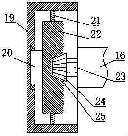
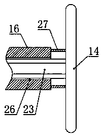
[0022] In this example, if figure 2 with 3 As shown, the cross-section of the linkage rod 23 is a regular polygonal shape, as long as it is not circular, the inner side of the positive and negative threaded rod 16 is provided with a sliding cavity 26 that cooperates with the linkage rod 23 to slide, so that the linkage rod 23 rotates Can drive positive and negative threaded rod 16 to rotate during.

[0023] One end of the positive and negative threaded rod 16 close to the rotating wheel 14 is also circumferentially dist...


PUM


Abstract

The invention relates to the field of cable mounting supports and particularly relates to a quick cable mounting device. The device comprises a device body, an elastic limiting assembly is fixedly installed at one end of the device body. The elastic limiting assembly is fixedly installed on the supporting frame assembly. Positive and negative threaded rods are arranged in an inner cavity of the device body; movable seats are in threaded connection with the two sides of the positive and negative threaded rod in a matched manner respectively; an upper connecting rod and a lower connecting rod are fixedly installed on the upper sides and the lower sides of the two movable bases correspondingly. Upper clamping plates are oppositely installed at the upper ends of the two upper connecting rods.Linkage rods are further arranged on the inner sides of the right-hand and left-hand threaded rods in a matched and sliding mode, rotating wheels are fixedly installed at the ends, away from the elastic limiting assemblies, of the linkage rods, and connectors capable of being in linkage fit with the elastic limiting assemblies are fixedly installed at the ends, close to the elastic limiting assemblies, of the linkage rods. According to the invention, quick installation and fixation of the cable are facilitated, the cable can be reliably and elastically supported, and the service life of the cable is prolonged.

Description

technical field [0001] The invention relates to the field of cable installation brackets, in particular to a device for quickly installing cables. Background technique [0002] A cable is an electrical energy or signal transmission device, usually composed of several or several groups of wires. Cables are securely and securely mounted to utility poles or building walls, or anchored to existing street yards. However, the existing method used in most places is to wind the household wiring on the main line, which will bring a lot of work to maintenance and emergency repair personnel, and there is a greater potential safety hazard. [0003] The existing cable installation bracket has a traditional structure, which is inconvenient for quick installation and fixing of the cable, and cannot provide reliable elastic support for the cable. The environmental adaptation effect is poor, which increases the wear and tear of the cable and affects the service life of the cable. Therefore...

Claims


Application Information

Patent Timeline
Patent Type & Authority Applications(China)
IPC IPC(8): H02G3/32H02G7/05
CPCH02G3/32H02G7/05
Inventor 晏秀芳
Owner 张于峰
Why Eureka
Try Eureka