Airway patency device for respiratory support in intensive care department

A medical and severe technology, applied in medical science, suction equipment, hypodermic injection equipment, etc., can solve the problems of high suction force and patient discomfort, and achieve the effect of stable foreign body absorption and good comfort

Inactive Publication Date: 2020-09-01
滨州医学院附属医院
View PDF12 Cites 2 Cited by
  • Summary
  • Abstract
  • Description
  • Claims
  • Application Information

AI Technical Summary

Problems solved by technology

[0007] The purpose of the present invention is to provide an airway stent for respiratory support in intensive care medicine to solve the problem that the existing airway stent cannot quickly and completely suck out foreign bodies, and there will be suction when the foreign body enters the intubation Problems that are too large and cause discomfort to the patient

Method used


Image

  • Airway patency device for respiratory support in intensive care department
  • Airway patency device for respiratory support in intensive care department
  • Airway patency device for respiratory support in intensive care department

Examples


Embodiment 1

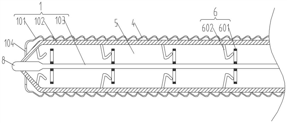
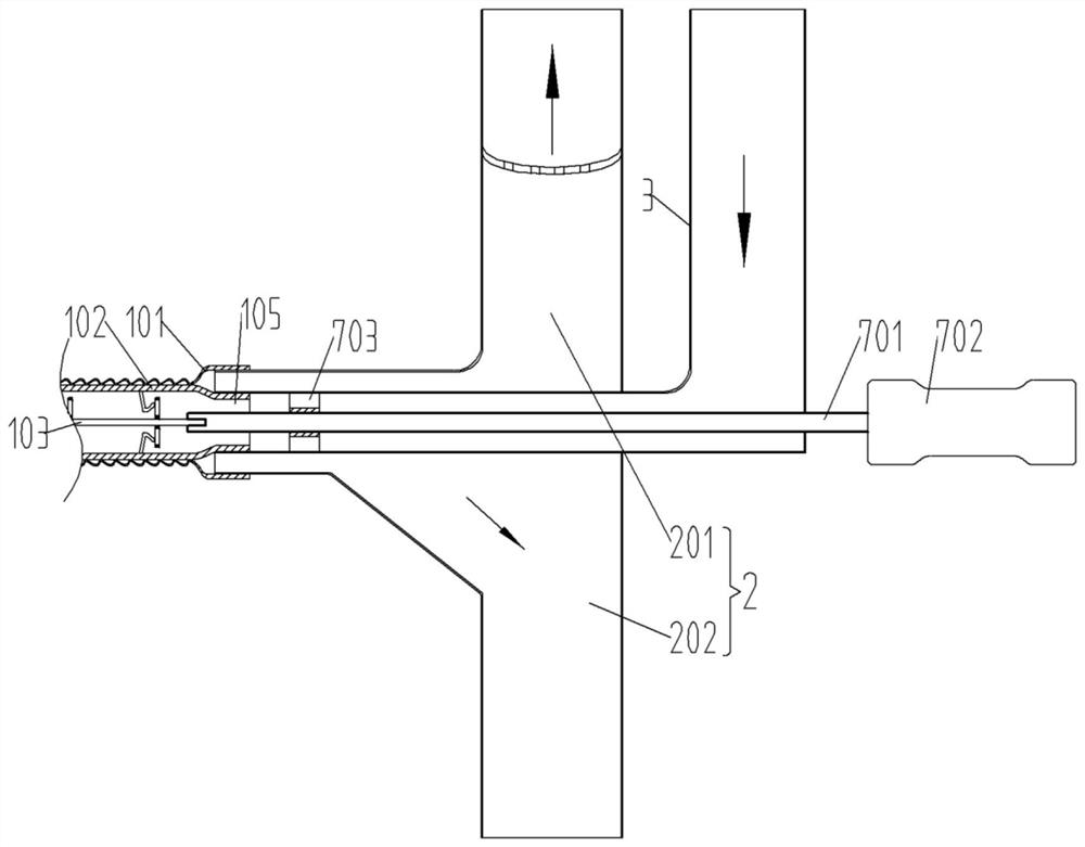
[0030] The embodiment is basically as attached figure 1 and figure 2 Shown: an airway stent for respiratory support in intensive care medicine, including an intubation tube 1 , an outer connecting tube 2 and a middle connecting tube 3 .

[0031] Such as figure 1 The cannula 1 includes an outer tube 101 , a middle tube 102 and an inner core 103 in sequence from outside to inside. The outer tube 101, the middle tube 102 and the inner core 103 are all made of silica gel.

[0032] Between the outer tube 101 and the middle tube 102 is an air suction chamber 4 . Inside the middle tube 102 is a breathing management support chamber 5 .

[0033] The left and right ends of the outer tube 101 are the outer air inlet 104 and the outer connection port respectively, and the left and right ends of the middle layer tube 102 are the middle air outlet and the middle connection port 105 respectively. The left end of the outer tube 101 is integrally connected with the left end of the middle...

Embodiment 2

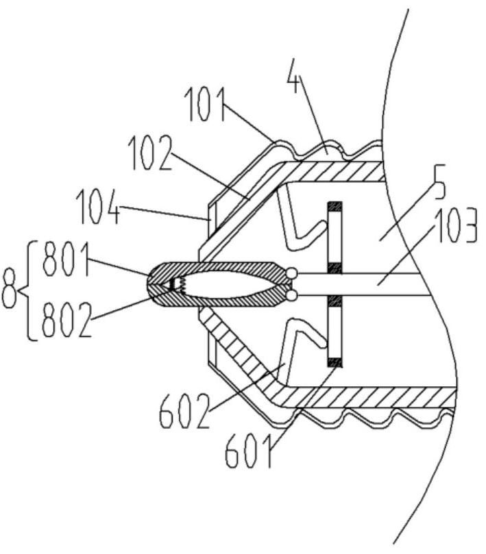
[0044] Such as image 3As shown, the difference between this embodiment and Embodiment 1 is that the terminal head 8 is composed of two expansion clips 801, the expansion clips 801 are hinged with the inner core 103, and the two expansion clips 801 are connected by a compression spring 802, and the compression spring 802 is close to the free end of expansion clip 801 . When absorbing foreign matter, push the inner core 103 to the left through the handle 703, so that the free ends of the expansion clips 801 protrude from the middle tube 102, and the free ends of the two expansion clips 801 are away from each other under the action of the compression spring 802, thereby The patient's action is expanded, and the foreign matter is further sucked into the suction chamber 4 quickly and thoroughly.


PUM


Abstract

The invention belongs to the technical field of medical equipment, and particularly discloses an airway patency device for respiratory support in an intensive care department. The device comprises anintubation tube, an outer connecting tube, a middle connecting tube, a first pulling piece and a second pulling piece; and the intubation tube sequentially comprises an outer-layer tube, a middle-layer tube and an inner core from outside to inside. An inspiration cavity is formed between the outer-layer tube and the middle-layer tube, and a respiration management supporting cavity is formed in themiddle-layer tube. Two ends of the outer-layer pipe are respectively an outer air inlet and an outer connecting port, and two ends of the middle-layer pipe are respectively a middle air outlet and amiddle connecting port. The outer layer pipe is connected with the outer connecting pipe through the outer connecting port, and the middle layer pipe is connected with the middle connecting pipe through the middle connecting port. The airway patency device is not prone to being blocked by foreign matters, the foreign matters can be stably sucked, the situations that negative pressure is wizened, and the suction force of the head of a cannula is not stable are avoided, and the comfort degree of a patient is good.

Description

technical field [0001] The invention belongs to the technical field of medical equipment, in particular to an airway stent for respiratory support in intensive care medicine. Background technique [0002] The airway is the human respiratory passage and is an accessory organ of the lung, including the trachea, larynx and nasal passages. In the Department of Critical Care Medicine, the most common medical method is to use airway stents to provide respiratory management and respiratory management support for acute respiratory insufficiency or other acute and severe patients. Since patients in the intensive care unit are often accompanied by respiratory sputum or blood clot obstruction, which not only affects the normal operation of the airway patency device, but also brings great inconvenience to the doctor's treatment, so the respiratory management and respiratory management support for patients Before that, it is also necessary to ensure that the airway is unobstructed, that...

Claims


Application Information

Patent Timeline
Patent Type & Authority Applications(China)
IPC IPC(8): A61B17/50A61B17/24A61M1/00
CPCA61M1/0023A61B17/24A61B17/50A61M1/84
Inventor 韩沙沙高福泉夏永富刘伟丽
Owner 滨州医学院附属医院
Why Eureka
Try Eureka