A bridge deck drainage structure

A drainage structure and bridge technology, which is applied in bridges, bridge construction, bridge parts, etc., can solve problems such as easy fracture of the joint between the branch pipe and the main pipe, impact of the branch pipe, shaking of the branch pipe, etc., to achieve smooth flow, reduce impact force, avoid cracked or damaged effect

Active Publication Date: 2021-10-08
CHONGQING VOCATIONAL INST OF ENG
View PDF8 Cites 0 Cited by
  • Summary
  • Abstract
  • Description
  • Claims
  • Application Information

AI Technical Summary

Problems solved by technology

[0004] The present invention intends to provide a bridge deck drainage structure to solve the problem that during the current strong stormy weather, the large amount of rainwater and the fast flow rate will cause a large impact on the branch pipes, causing the branch pipes to sway, causing the connection between the branch pipes and the main pipe to break easily or damage issues

Method used


Image

  • A bridge deck drainage structure
  • A bridge deck drainage structure
  • A bridge deck drainage structure

Examples


Embodiment 1

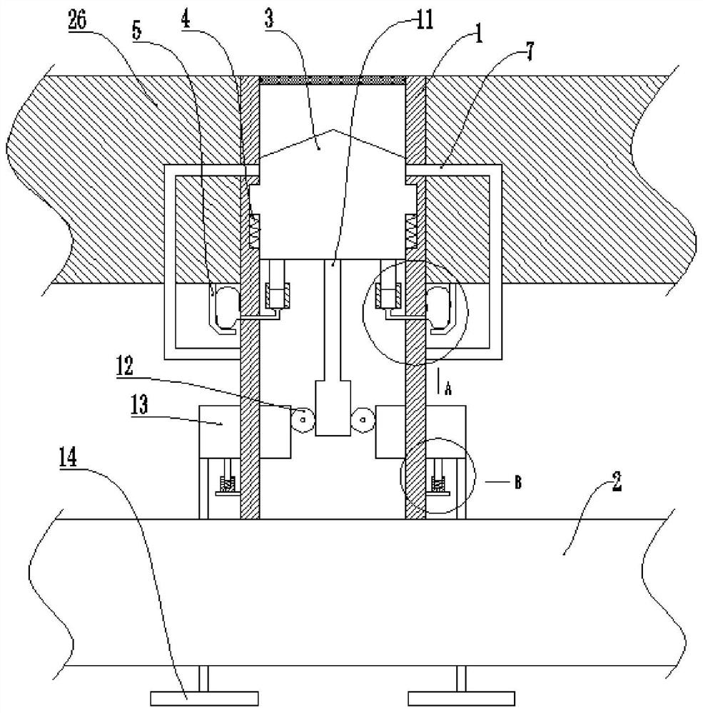
[0038] Basic as attached figure 1 , attached figure 2 And attached image 3 Shown: a bridge deck drainage structure, including several branch pipes 1 fixed on the bridge 26 and main pipes 2 connected to several branch pipes 1, and the top of the branch pipes 1 is equipped with a filter screen, and the main pipe 2 is located below the branch pipes 1.

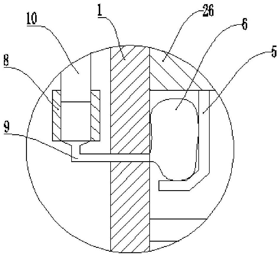
[0039] An annular groove is vertically formed on the inner wall of the branch pipe 1, and a slider 3 is vertically slidably connected in the annular groove, and a first spring 4 is fixedly connected between the slider 3 and the annular groove, and the top of the slider 3 is conical. It also includes a stabilizing mechanism arranged symmetrically along the centerline of the slider 3. The stabilizing mechanism includes a stopper 5, an airbag 6 located between the branch pipe 1 and the stopper 5, and an inflatable part that inflates the airbag 6 as the slider 3 moves vertically. The block 5 is fixed on the bridge 26 by bolts. The...

Embodiment 2

[0049] Basic as attached Figure 4 , attached Figure 5 And attached Figure 6 As shown: the structure and implementation of Embodiment 2 are basically the same as Embodiment 1, the difference is that: it also includes a collection box 18 fixed at the bottom of the bridge 26 by bolts, and the side wall of the side pipe 7 is communicated with a collection pipe 19 , and the collection pipe 19 communicates with the collection box 18; the side pipe 7 is fixedly connected with a screen 20, and the end of the collection pipe 19 away from the collection box 18 is located above the screen 20.

[0050] In the collecting box 18, a lifting plate 21 is vertically slidably connected, and a third spring 22 is fixedly connected between the lifting plate 21 and the collecting box 18. There is a discharge port above the right side wall of the collecting case 18, and the discharge port is located at Lifting plate 21 tops. The bottom of the lifting plate 21 extends downwards with a spheroid 2...


PUM


Abstract

The invention relates to the technical field of bridge drainage equipment. Disclosed is a bridge deck drainage structure, comprising several branch pipes fixedly connected to the bridge and main pipes connected to the several branch pipes, the main pipe is located below the branch pipes; an annular groove is provided on the inner wall of the branch pipe, and a sliding block is slidably connected in the annular groove, and There is a first spring between the slider and the ring groove; it also includes a stabilizing mechanism symmetrically arranged along the center line of the slider. The stabilizing mechanism includes a block fixed on the bridge, an air bag between the branch pipe and the block, and The block moves vertically to inflate the air bag; both sides of the branch pipe are connected with side pipes that open and close with the vertical movement of the slider, and the end of the side pipe away from the slider is located below the air bag and communicates with the branch pipe; The spacing is greater than the spacing between the baffle plate and the branch pipe. This solution mainly solves the current problem that during strong stormy weather, the rainwater has a large impact on the branch pipe due to the large amount and fast flow rate, causing the branch pipe to shake, resulting in the problem that the connection between the branch pipe and the main pipe is easily broken or damaged.

Description

technical field [0001] The invention relates to the technical field of bridge drainage equipment. Background technique [0002] Bridges generally refer to structures erected on rivers, lakes and seas to allow vehicles and pedestrians to pass smoothly. There is also a drainage structure installed on the bridge surface; using the drainage structure to drain the accumulated water or rainwater on the bridge surface, on the one hand, it reduces the probability of vehicle skidding, and on the other hand, it can also prolong the service life of the bridge. Therefore, the bridge surface The drainage structure is very important. [0003] At present, drainage pipes are usually used for drainage structures. Drainage pipes generally include several branch pipes installed on bridges and main pipes connected to several branch pipes. The main pipe is located below the bridge deck and suspended in the air. The accumulated water or rainwater is transported from the main pipe to other places...

Claims


Application Information

Patent Timeline
Patent Type & Authority Patents(China)
IPC IPC(8): E01D19/08
CPCE01D19/086
Inventor 王贵珍李红立皮育晖
Owner CHONGQING VOCATIONAL INST OF ENG
Why Eureka
Try Eureka