Stator for a motor or electromagnetic generator with individual winding support snap-fitted to an associated tooth

An electromagnetic generator, winding support technology, applied in the manufacture of motor generators, motor components, windings, etc., to achieve the effect of increasing convenience, expanding the scope of use, and improving manufacturing efficiency

Pending Publication Date: 2020-09-01
万络公司
12 Cites 2 Cited by

AI-Extracted Technical Summary

Problems solved by technology

However, much progress has been made in the design of rotors and the output of motors and machines by im...

Abstract

The invention relates to a stator (8) for a motor or electromagnetic generator comprising windings (4) and a magnetic circuit, the stator (8) comprising a cylinder head with a circular or polygonal shape and winding support teeth (3). Each winding (4) rests on a tooth (3) while at least partially surrounding a winding support (13, 14), each winding support (13, 14) comprising or being associated with snap-fitting means (15') which cooperate with complementary snap-fitting means (3') supported by a tooth (3) associated with the winding support (13, 14) so that the winding support (13, 14) is solidly fixed to the associated tooth (3).

Application Domain

Technology Topic

Electric generatorElectromagnetic generator +4

Image

  • Stator for a motor or electromagnetic generator with individual winding support snap-fitted to an associated tooth
  • Stator for a motor or electromagnetic generator with individual winding support snap-fitted to an associated tooth
  • Stator for a motor or electromagnetic generator with individual winding support snap-fitted to an associated tooth

Examples

  • Experimental program(1)

Example

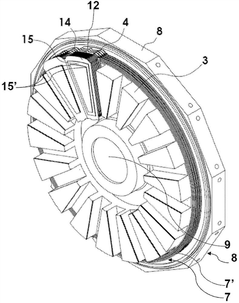
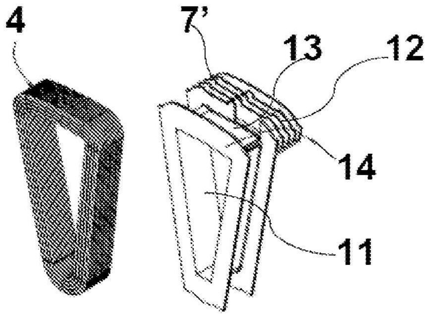
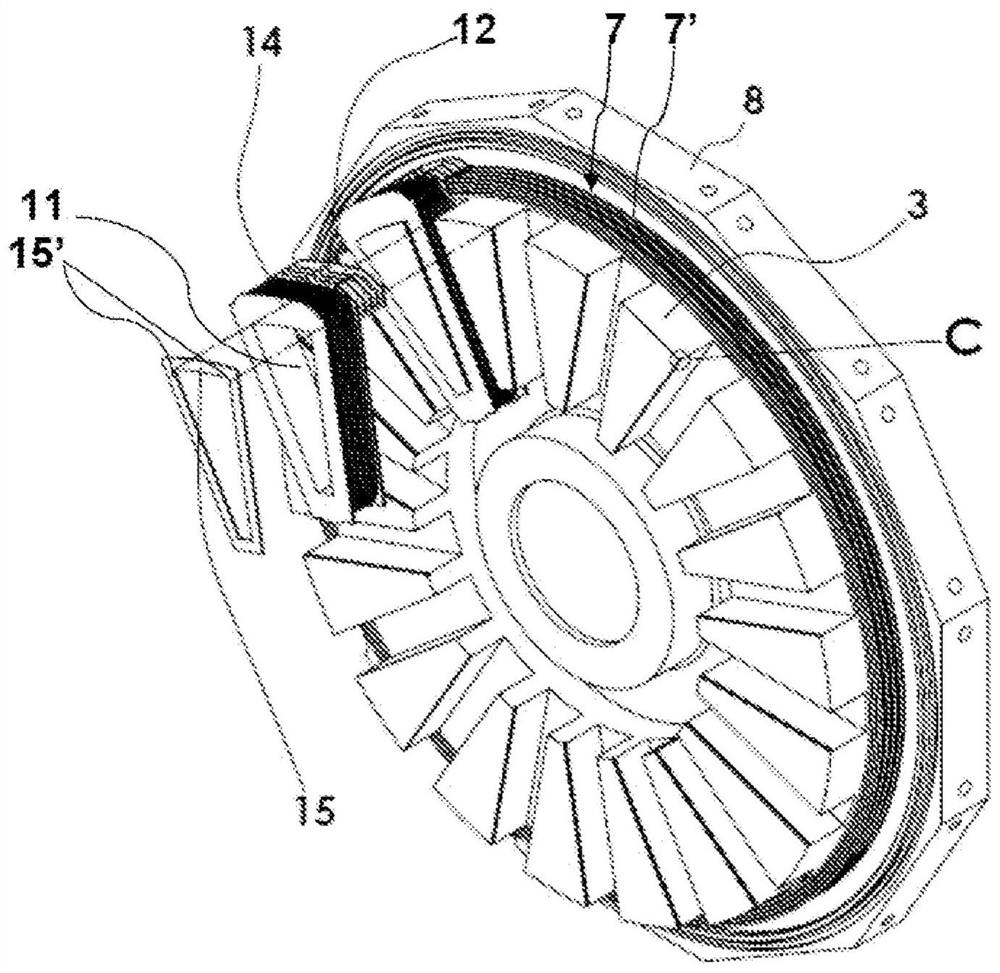
[0074] For the first embodiment, the associated tooth 3 may comprise a slot near each side edge of its face facing the winding 4, two slots 3' each receiving one of the snap-fit ​​parts and forming a complementary snap fit. Snap fit means 3'. The slots 3' may preferably extend over the laterally inclined surfaces of the teeth 3, but not necessarily over the surfaces of the teeth facing the windings.
[0075] This is valid for all winding supports 4 and all teeth 3 . The flat cover portion 14 associated with a tooth 3 may be adjacent to the flat cover portion 14 associated with each adjacent tooth 3 . A set of cover parts can then form a ring which completely covers the teeth 3 and the spaces separating them.
[0076] The teeth 3 can be made of iron or ferrite plastomer, while the winding support 4 can be made of strong plastic material. Each tooth 3 may be formed from coiled or laminated sheet metal.
[0077] The locking element 15 (when present) is advantageously metallic so that it is strong and enables a secure snap fit in place. The winding 4 may be a three-phase winding 4 .
[0078] like Figure 1 to Figure 3 As shown, the winding supports 13, 14 may comprise a rib winding phase support 12 on the end facing the yoke. The set of ribbed phase supports 12 of the winding 4 may form a ring 7 at the base of the tooth 3, against the yoke of the stator 8 supporting the tooth 3, the ring 7 having concentric ribs 7', said ring being connected to the stator 8 with a central void The center is concentric.
[0079]The invention relates to an electric machine or generator comprising at least one rotor and at least one stator 8 as described above, said electric machine being an axial flux machine. The electric machine may comprise at least two stators 8 and at least one rotor.
[0080] In a particularly advantageous embodiment not shown in the drawings, said one or more rotors comprise magnet structures forming magnetic poles, each magnet structure consisting of a plurality of single magnets. A cover disk may be arranged axially on each of two opposite axial faces of the at least one rotor.
[0081] Different types of materials can be used for a single magnet, for example selected from: samarium cobalt (Sm-Co), aluminum, nickel and cobalt alloys, hard ferrite and neodymium iron boron materials, it is important that these materials must be able to withstand Machined into a lug having a smaller width or diameter compared to its length.
[0082] The cover plate can be made of composite material. Furthermore, the cover plate and the magnet structure may be coated with or encased in an outer layer of composite material, which defines the outer contour of the at least one rotor.
[0083] The invention also relates to a method of winding the windings 4 on the corresponding teeth 3 of the stator 8 of an electric machine or electromagnetic generator as described above.
[0084] Said method comprises the step of winding a conductive wire, advantageously made of copper, as a winding 4 around a part of a winding support 13 , 14 inserted at least partially or not around the associated tooth 3 .
[0085] When the winding 4 has been inserted partly around the tooth, the winding supports 13 , 14 can be removed from the associated tooth 3 .
[0086] In the first case, said winding 4 is inserted at least partially around a tooth 3 when the winding supports 13 , 14 were not previously inserted at least partially around said tooth.
[0087] The next step is the snap fit of the winding supports 13, 14 on the teeth 3 by pushing the winding supports 13, 14 towards the yoke of the stator 8, i.e. by inserting the winding supports 13, 14 until they snap into place. The snap fit means 15' cooperate with complementary snap fit means 3' provided on the teeth.

PUM

no PUM

Description & Claims & Application Information

We can also present the details of the Description, Claims and Application information to help users get a comprehensive understanding of the technical details of the patent, such as background art, summary of invention, brief description of drawings, description of embodiments, and other original content. On the other hand, users can also determine the specific scope of protection of the technology through the list of claims; as well as understand the changes in the life cycle of the technology with the presentation of the patent timeline. Login to view more.

Similar technology patents

Classification and recommendation of technical efficacy words

  • Improve manufacturing efficiency
  • Improve convenience

Rimless spectacles

InactiveUS20080198323A1Difficult to manufactureImprove manufacturing efficiencyLens assembliesLens plateElectrical and Electronics engineering
Owner:DONGGUAN JI SHENG OPTICAL

Trocar system and method of use

InactiveUS20080009797A1Improve manufacturing efficiencyFacilitate punctureInfusion syringesSurgical needlesAbdominal trocarEngineering
Owner:UNITED STATES SURGICAL CORP

3D printing method for building beam component

Owner:无锡华工大光电智能科技有限公司

Hydrogen filling apparatus and hydrogen filling method

ActiveUS20100307636A1Improve convenienceAccurate timingLiquid fillingGas handling/storage effectsHydrogen tankChemistry
Owner:HONDA MOTOR CO LTD

Method for treating Sjogren's syndrome

InactiveUS20060062787A1Low costImprove convenienceBiocideSenses disorderVisual analogue scaleRegimen
Owner:GENENTECH INC
Why Eureka
Try Eureka