

Clamping device and clamping method thereof
A clamping device and suction cup technology, which is applied in the field of machining, can solve problems such as workpiece clamping deformation, and achieve the effects of small clamping deformation, elimination of influence and convenient operation.
- Summary
- Abstract
- Description
- Claims
- Application Information
AI Technical Summary
Problems solved by technology
Method used
Image

Examples
Embodiment 1
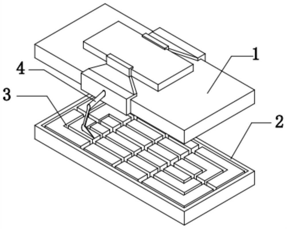
[0039] The embodiment is basically as attached figure 1 Shown: a clamping device, including an upper suction cup 1, a lower suction cup 2 and a suction cup valve body; There is a positioning structure for workpiece positioning, and the positioning structure is deformable.
[0040] The positioning structure includes positioning claws 4 symmetrically arranged on the upper suction cup 1, and the positioning claws 4 are telescopic. Through the retractable positioning claw 4, not only planar parts can be clamped, but also special-shaped parts with non-planar structures can be clamped.
[0041] Each positioning claw 4 has at least one movable joint. In this embodiment, there are two movable joints of the positioning claw 4, and the positioning claw 4 is arranged on the front side and the rear side of the upper suction cup 1 and the lower suction cup 2 respectively, without affecting the clamping between the upper suction cup 1 and the lower suction cup 2. The processing of the wo...
Embodiment 2
[0069] The difference between this embodiment and Embodiment 1 is that the anti-slip layer is a hollow layer filled with mucus, and the inner side of the anti-slip layer has uneven anti-slip lines, and there are small holes in the depressions that expand to allow the mucus to flow out slowly. When the positioning claw 4 is clamping the workpiece, the anti-slip layer of the positioning claw 4 is in contact with the workpiece, and the area in contact with the workpiece is the convex part of the anti-slip texture, and the convex part is squeezed in contact with the workpiece, so that it is not in contact with the workpiece. The concave part of the groove is stretched and expanded, so that the mucus flows out from the small hole and adheres to the workpiece to be processed, which effectively increases the firmness of the holding between the positioning claw 4 and the workpiece to be processed. And because the anti-slip lines are uneven, the number of small holes in the recesses is ...
Embodiment 3
[0071] The difference with Embodiment 1 is that the positioning claw 4 in this embodiment is similar to the structure of the existing manipulator, but a movable joint strut near the end of the positioning claw 4 is a hollow structure, and the end of the positioning claw 4 is pasted with In addition to the anti-slip layer, a spray gun that can spray objects outward is also installed. The caliber of the spray gun is slightly larger than the caliber of the commonly used spray gun, and the diameter of the spray gun is about between centimeters. The movable joint strut closest to the spray gun, that is, the movable joint strut closest to the positioning claw 4 ends, communicates with the spray gun, and is used as the chamber of the spray gun. A sticky rubber net is placed in the movable joint pole. When the positioning claw 4 is close to the workpiece to be processed, the rubber net can be sprinkled on the surface of the workpiece to be processed through the spray gun. Because t...
PUM
 Abstract
Description
Claims
Application Information