
Automatic polishing device for metal plate

A metal plate, automatic technology, used in metal processing equipment, grinding/polishing equipment, grinders, etc., can solve the problems of waste of money, rough equipment, poor grinding effect, etc., to achieve the effect of convenient collection and wide application range

Inactive Publication Date: 2020-09-04
PAN AN AIKEN MECHANICAL EQUIP CO LTD
View PDF0 Cites 4 Cited by
  • Summary
  • Abstract
  • Description
  • Claims
  • Application Information

AI Technical Summary

Problems solved by technology

[0002] When processing plates such as metal plates, alloy plates, etc., the usual process is to grind the surface of the plate to make the surface smoothness of the plate meet the specified requirements. The existing processing workshops may use manual grinding. It is time-consuming and labor-intensive to grind the plate, or use grinding equipment to polish the plate, but the existing equipment is either too rough, the grinding effect is not good, or it is too expensive, wasting a lot of money, and manual processing is required during grinding. For different thicknesses Metal plate grinding requires manual adjustment, which is very inconvenient

Method used


Image

  • Automatic polishing device for metal plate
  • Automatic polishing device for metal plate
  • Automatic polishing device for metal plate

Examples


Embodiment Construction

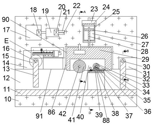
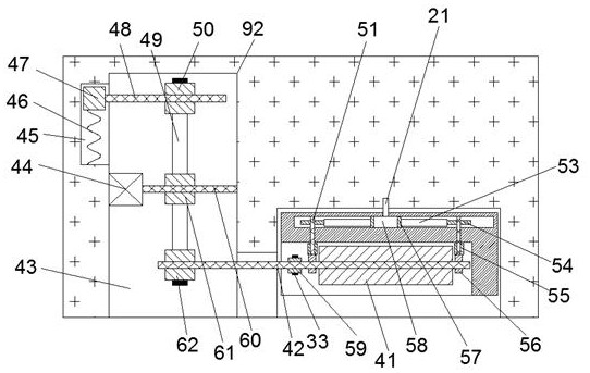
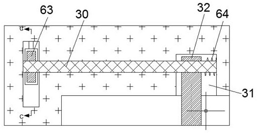
[0017] Combine below Figure 1-6 The present invention is described in detail, and for convenience of description, the orientations mentioned below are now stipulated as follows: figure 1 The up, down, left, right, front and back directions of the projection relationship itself are the same.

[0018] refer to Figure 1-6 , according to an embodiment of the present invention, a metal plate automatic grinding equipment includes a casing 10, the casing 10 is provided with a grinding cavity 12 at the left and right ends communicating with the outside world, and the upper end wall of the grinding cavity 12 is provided with Detection chamber 14, a sliding chamber 84 is provided in the right end wall of the detection chamber 14, an accommodation chamber 86 is provided in the right end wall of the sliding chamber 84, a lifting chamber 27 is arranged in the upper end wall of the accommodation chamber 86, and the lifting chamber 27 is provided with a control chamber 23 in the upper en...


PUM


Abstract

The invention discloses an automatic polishing device for a metal plate. The automatic polishing device comprises a machine shell. A polishing cavity with the left end and the right end communicatingwith the outside is formed in the machine shell. A detection cavity is formed in the upper end wall of the polishing cavity. A sliding cavity is formed in the right end wall of the detection cavity. Acontaining cavity is formed in the right end wall of the sliding cavity. A lifting cavity is formed in the upper end wall of the containing cavity. A control cavity is formed in the upper end wall ofthe lifting cavity. A middle cavity is formed in the left end wall of the lifting cavity. By means of the automatic polishing device for the metal plate, due to the arrangement of a polishing cylinder which can ascend and descend, steel plates with different thicknesses can be polished; in addition, due to the arrangement of a descending plate which can achieve different descending heights according to the thicknesses of the steel plates, the steel plates with different thicknesses can be automatically adjusted to be polished; in addition, an adjusting shaft capable of adjusting the polishingdegree is arranged so that the polishing degree can be adjusted, and the application range is wider; and an electromagnet capable of collecting rust generated by polishing is arranged, rust and ironscrap generated during polishing can be collected conveniently

Description

technical field [0001] The invention relates to the technical field of numerical control processing, in particular to automatic grinding equipment for metal plates. Background technique [0002] When processing plates such as metal plates, alloy plates, etc., the usual process is to grind the surface of the plate to make the surface smoothness of the plate meet the specified requirements. The existing processing workshops may use manual grinding. It is time-consuming and labor-intensive to grind the plate, or use grinding equipment to polish the plate, but the existing equipment is either too rough, the grinding effect is not good, or it is too expensive, wasting a lot of money, and manual processing is required during grinding. For different thicknesses Metal plate grinding requires manual adjustment, which is very inconvenient. Contents of the invention [0003] The object of the present invention is to provide an automatic metal plate grinding equipment for overcoming ...

Claims


Application Information

Patent Timeline
Patent Type & Authority Applications(China)
IPC IPC(8): B24B27/033B24B7/06B24B27/00B24B41/06B24B47/12B24B47/22B24B55/06B24B55/12
CPCB24B7/06B24B27/0069B24B27/0076B24B27/033B24B41/06B24B47/12B24B47/22B24B55/06B24B55/12
Inventor 洪剑达
Owner PAN AN AIKEN MECHANICAL EQUIP CO LTD
Learn More