Perforating device for concrete wall surface

A drilling device and concrete technology, applied in the direction of stone processing tools, work accessories, manufacturing tools, etc., can solve the problems of irregular orbits of electric drills, poor standing comfort, physical exertion, etc., to simplify the drilling process, avoid The effect of pushing the rotation and reducing the working intensity

Active Publication Date: 2020-09-04
淄博聚德建筑安装有限公司
View PDF5 Cites 1 Cited by
  • Summary
  • Abstract
  • Description
  • Claims
  • Application Information

AI Technical Summary

Problems solved by technology

[0004] The purpose of the present invention is to provide a concrete wall punching device to solve the problem that when opening a large-diameter round hole in the above-mentioned background technology, the worker needs to manually rotate and adjust the drilling position of the electric drill on the wall for many times, so that the electric drill can Circumferential drilling, the operation process is cumbersome and inconvenient, and the manual adjustment of the electric drill's orbit is irregular, and the inside and outside will be uneven, resulting in a round hole that is not a perfect circle, and the worker usually needs to stand and push the electric drill with his hands when drilling, which consumes a lot of physical strength , Poor comfort when standing for a long time, easy to fatigue

Method used


Image

  • Perforating device for concrete wall surface
  • Perforating device for concrete wall surface
  • Perforating device for concrete wall surface

Examples


Embodiment 1

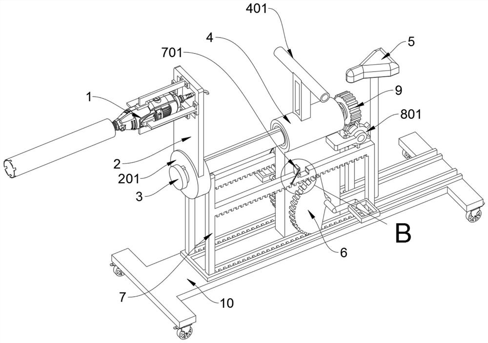
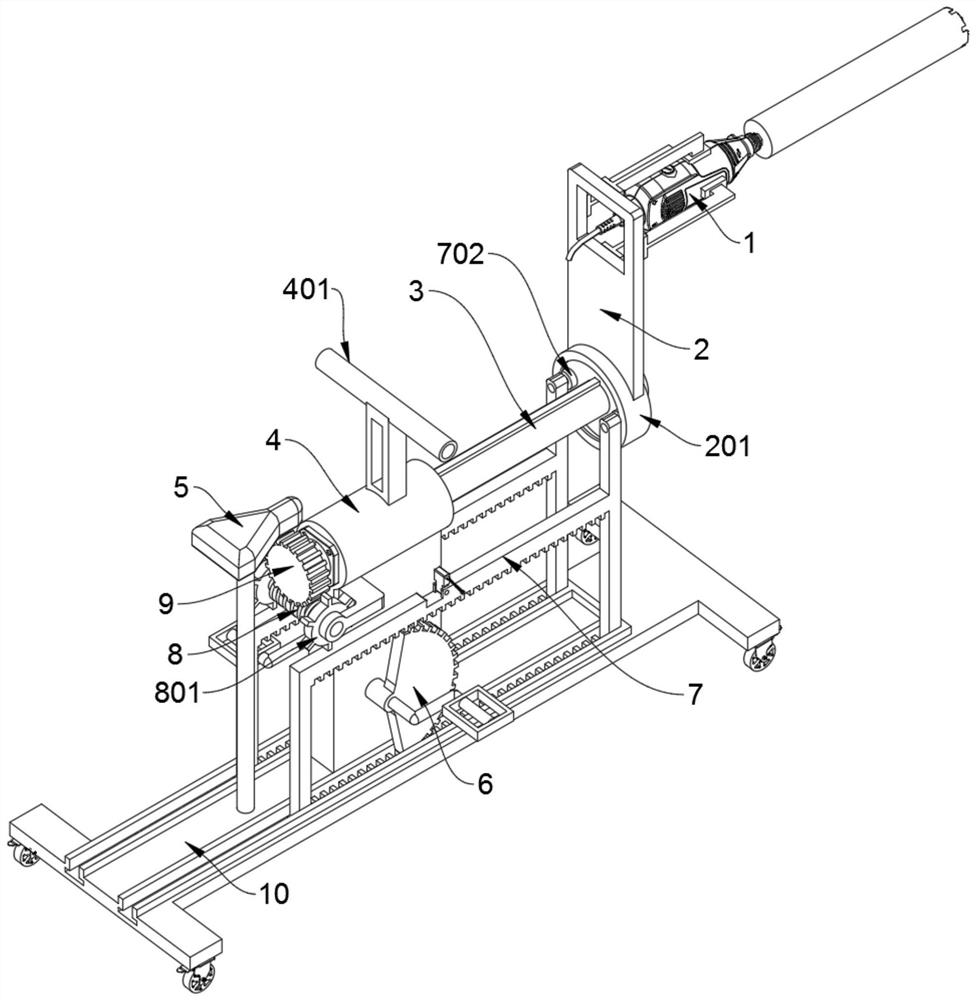
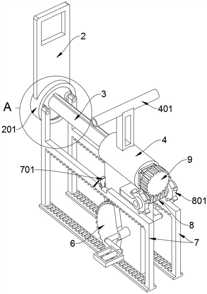
[0030] See Figure 1 to Figure 6 with Figure 8 , An embodiment provided by the present invention: a concrete wall punching device, comprising a mounting plate 2, a supporting shaft 3, a positioning shaft sleeve 4, a push frame 7 and a base 10, and the top end of the mounting plate 2 is upward There is an electric drill 1 installed in the front locking; the mounting plate 2 includes a swivel 201 and an annular baffle 202, the bottom of the mounting plate 2 is welded and fixed to a swivel 201, the swivel 201 is sleeved on the supporting shaft 3 and connected by a key Drive, and the back side of the swivel 201 is supported and welded with an annular baffle 202, through the swivel 201, the mounting plate 2 can drive the electric drill 1 to slide back and forth along the supporting shaft 3 for drilling; the second half of the supporting shaft 3 is rotated and installed On the positioning shaft sleeve 4, and the rear end of the supporting shaft 3 is sleeved with a worm wheel 9; the ...

Embodiment 2

[0033] On the basis of Example 1, please refer to Figure 4 , Figure 7 with Picture 9 , An embodiment provided by the present invention: a device for punching a concrete wall, further comprising a push frame 7, two push frames 7 slidably placed on the base 10 in two T-shapes. In the chute, the push frame 7 includes a top block 701 and a guide wheel 702. The middle section of the top end of the two push frames 7 is provided with a placement slot, and the two top blocks 701 are erected on the two by springs. Placed in the slot; the top end of the vertical support rod on the front side of the push frame 7 at two places are rotated to install a guide wheel 702.

[0034] Furthermore, the inner sides of the upper and lower side rods of the two push frames 7 protrude to support a row of positioning teeth, and the two bevel gears 6 can alternately rotate and mesh corresponding to the upper and lower rows of positioning teeth, and the two bevel gears 6 can be meshed and driven. The two ...


PUM


Abstract

The invention discloses a perforating device for a concrete wall surface, relates to the technical field of perforating equipment, and solves the problems that an opened circular hole is not perfectly-circular because internal-external staggering is caused due to the irregularity of manual adjustment for a surrounding track of an electric drill, and high physical power consumption is caused because a worker generally needs to stand and violently pushes the electric drill with a hand during drilling. The perforating device for the concrete wall surface comprises an installation plate, a supportrotary shaft, a pushing frame and a base, wherein an electric drill is installed on a top end section of the installation plate in a manner of being locked forwards; the rear half section of the support rotary shaft is rotationally installed on a location shaft sleeve in a penetrating manner, and a worm gear is installed at the rear end of the support rotary shaft in a sleeved manner; and a saddle is installed on the rear half section of the base in a supporting manner, a location shaft sleeve is supported and welded to the middle part of the base, and two bevel gears are rotationally installed on a vertical supporting plate at the bottom of the location shaft sleeve in the form of left-right correspondence. According to the perforating device for the concrete wall surface, two guide wheels are capable of ensuring that a rotary ring can still be rotationally connected with two pushing frames during normal self-rotation.

Description

Technical field [0001] The invention relates to the technical field of punching equipment, in particular to a concrete wall punching device. Background technique [0002] Nowadays, some houses or construction sites will make round holes in the concrete due to their needs. Workers need to place the electric drill on the concrete first. After the worker fixes the electric drill on the concrete, the worker needs to start the electric drill to rotate. The electric drill rotates to drill the concrete. When a worker uses an electric drill to drill concrete, the worker generally needs to push the electric drill forward intermittently so that the electric drill can drill different thicknesses of concrete. When the worker uses the electric drill to drill a hole, the worker needs to replace the electric drill on the concrete After the worker repeats the above operation again, he can drill another hole in the concrete. When the worker uses an electric drill to drill a circle of holes in the...

Claims


Application Information

Patent Timeline
Patent Type & Authority Applications(China)
IPC IPC(8): B28D1/14B28D7/00
CPCB28D1/14B28D7/00
Inventor 邓艳兵
Owner 淄博聚德建筑安装有限公司
Why Eureka
Try Eureka