Traction pinch roller pressure adjusting mechanism

A technology of pressure adjustment and adjustment mechanism, applied in the direction of paper/cardboard container, container, bag making operation, etc., can solve the problems of affecting the traction efficiency and conveying effect, inconsistent pressing force, inconvenient operation, etc., to improve convenience and consistency, high degree of automation, convenient operation

Pending Publication Date: 2022-02-18
NANJING ZONO MACHINE EQUIP
View PDF0 Cites 0 Cited by
  • Summary
  • Abstract
  • Description
  • Claims
  • Application Information

AI Technical Summary

Problems solved by technology

[0003] In the prior art, each group of pressure roller adjustment devices in the traction roller pressure adjustment mechanism is independent, and is controlled by two compression handles respectively. The adjustment device corresponding to the wheel assembly is not only inconvenient to operate, but also easily causes inconsistencies in the pressure of each group, resulting in inconsistent pressing force during traction, which directly affects the traction efficiency and conveying effect, poor adjustment accuracy, and cumbersome operation

Method used


Image

  • Traction pinch roller pressure adjusting mechanism
  • Traction pinch roller pressure adjusting mechanism
  • Traction pinch roller pressure adjusting mechanism

Examples


Embodiment Construction

[0027] The preferred embodiments of the present invention will be described in detail below in conjunction with the accompanying drawings, so that the advantages and features of the present invention can be more easily understood by those skilled in the art, so as to define the protection scope of the present invention more clearly.

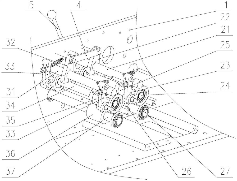
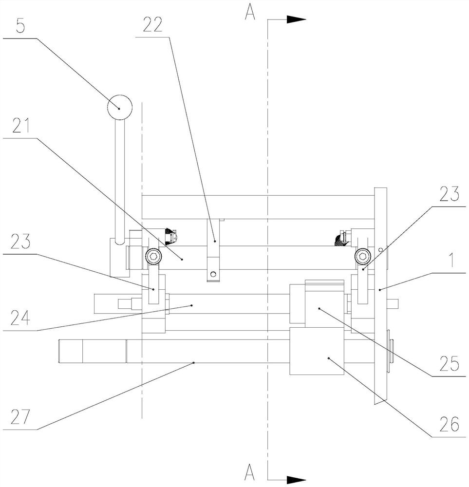
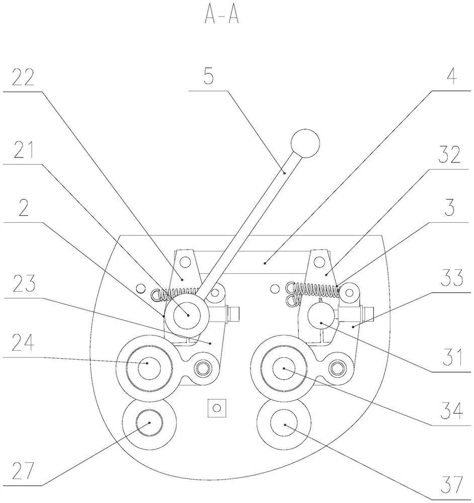
[0028] like Figure 1-3 The pressure adjustment mechanism of the traction rollers shown includes a wallboard 1 , an active adjustment mechanism 2 and a driven adjustment mechanism 3 connected to the wallboard 1 , and a connecting rod 4 .

[0029] The active adjustment mechanism includes a pressing handle 5, a driving shaft 21, an active swing arm shaft 22, an active swing arm assembly 23, an active pulling material pulling roller shaft 24, an active pulling material pulling pressure roller 25, and an active pulling material pulling pulley 26. The lower shaft 27 is actively pulled to pull the material. The two ends of the driving shaft 21 are arra...


PUM


Abstract

The invention relates to a traction pinch roller pressure adjusting mechanism, which comprises a wall plate, a driving adjusting mechanism, a driven adjusting mechanism and a connecting rod, wherein the driving adjusting mechanism and the driven adjusting mechanism are connected to the wall plate, the driving adjusting mechanism comprises a pressing handle, a driving shaft, a driving swing arm shaft, a driving swing arm assembly, a driving material pulling traction pressing roller shaft, a driving material pulling traction pressing wheel, a driving material pulling traction guide wheel and a driving material pulling traction lower shaft, the driven adjusting mechanism comprises a driven shaft, a driven swing arm shaft, a driven swing arm assembly, a driven material pulling traction press roll shaft, a driven material pulling traction press wheel, a driven material pulling traction guide wheel and a driven material pulling traction lower shaft, one end of the driving swing arm shaft is connected with the driving shaft, one end of the driven swing arm shaft is connected with the driven shaft, two ends of the connecting rod are hinged with the other end of the driving swing arm shaft and the other end of the driven swing arm shaft respectively,the traction pinch roller pressure adjusting mechanism has the advantages that the linkage adjustment can be realized, the pressure degree is stable, the adjusting precision is high, the operation is convenient, and the universality is strong.

Description

Technical field: [0001] The invention relates to the technical field of packaging bag processing equipment, in particular to a traction roller pressure adjustment mechanism. Background technique: [0002] The traction roller pressure adjustment mechanism is a common mechanism in the packaging paper bag production line, and is mainly used to adjust the pressure of each roller assembly used to draw the paper bag. [0003] In the prior art, each group of pressure roller adjustment devices in the traction roller pressure adjustment mechanism is independent and is controlled by two compression handles respectively. When this mechanism adjusts the pressure of each group of pressure rollers, it needs to individually adjust the The adjustment device corresponding to the wheel assembly is not only inconvenient to operate, but also easily causes inconsistent pressure of each group, resulting in inconsistent pressing force during traction, which directly affects traction efficiency and...

Claims


Application Information

Patent Timeline
Patent Type & Authority Applications(China)
IPC IPC(8): B31B70/00B31B70/02B31B70/74
CPCB31B70/02B31B70/006B31B70/74
Inventor 程荣武程荣文赵强胡平飞黎广寿许金
Owner NANJING ZONO MACHINE EQUIP
Why Eureka
Try Eureka