Clamping structure of cargo supporting device

A clamping structure and supporter technology, which is applied in the direction of freight vehicles, motor vehicles, load fixing, etc., can solve the problems of poor movement stability of the chuck, and achieve the goal of improving market competitiveness, good operation feel, and easy favor Effect

Active Publication Date: 2020-09-04
ZHEJIANG TOPSUN LOGISTIC CONTROL CO LTD
View PDF6 Cites 1 Cited by
  • Summary
  • Abstract
  • Description
  • Claims
  • Application Information

AI Technical Summary

Problems solved by technology

[0011] The purpose of the present invention is to solve the above-mentioned problems in the existing technology, and propose a clamping structure of a cargo support. The present invention solves the problem of poor movement stability of the chuck in the existing cargo support.

Method used


Image

  • Clamping structure of cargo supporting device
  • Clamping structure of cargo supporting device
  • Clamping structure of cargo supporting device

Examples


Embodiment 1

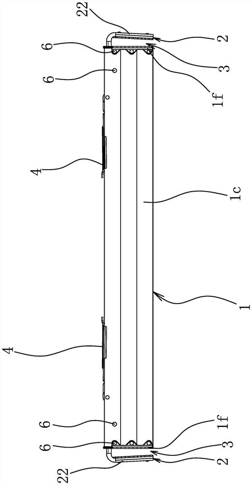
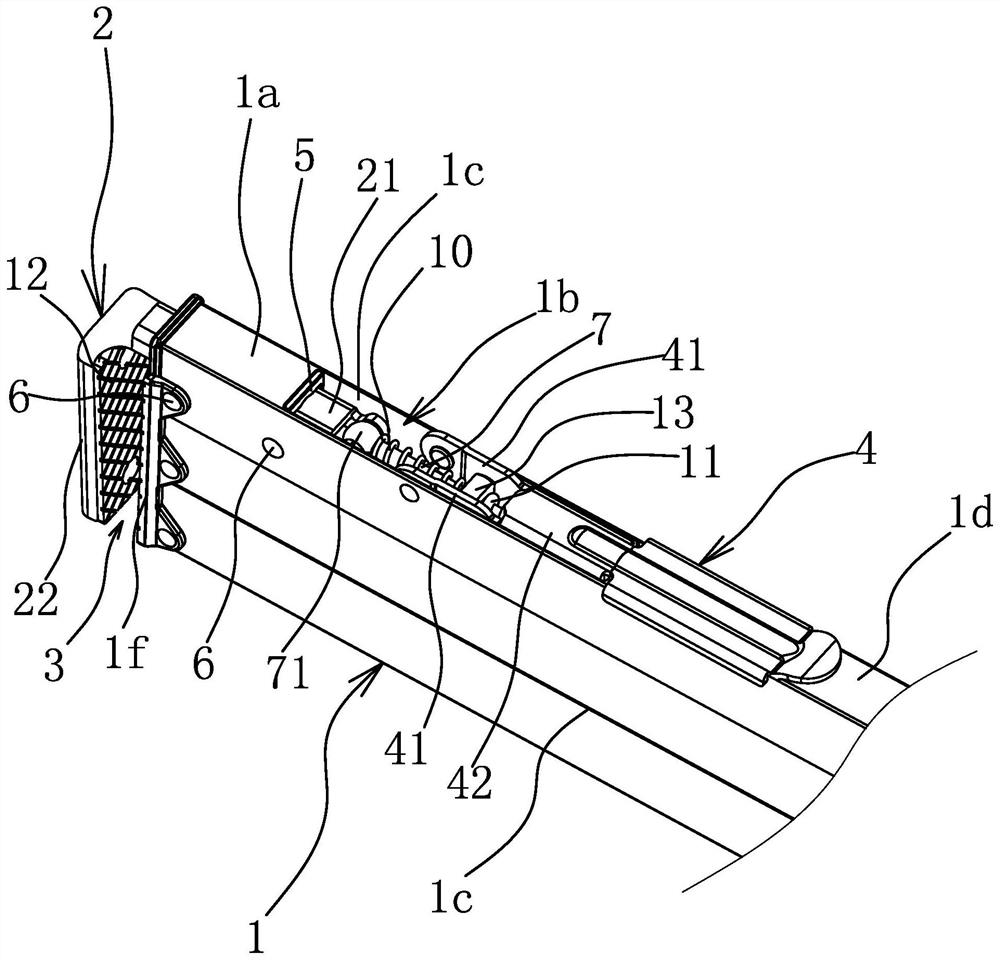
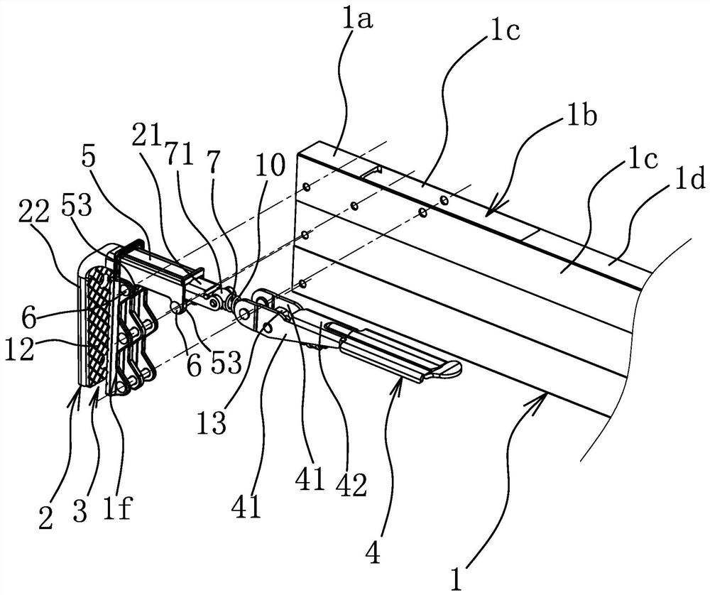
[0046] Such as figure 1 and figure 2 As shown, the cargo support includes a beam 1, and the two ends of the beam 1 are respectively provided with clamping structures with the same structure. The clamping structure includes a chuck 2 arranged at the end of the beam 1. The chuck 2 has a guide part 21 and a clamping part 22. The guide part 21 is strip-shaped and arranged along the axial direction of the beam 1. The beam 1 is a hollow structure and clamps The guide portion 21 of the head 2 extends into the beam 1 , and the clamping portion 22 is connected to one end of the beam 1 protruding outward from the beam 1 and is bent downward relative to the guide portion 21 . In order to increase the friction during the clamping process to ensure the stability of the clamping, a rubber pad 1f is fixedly connected to the end face of the beam 1, and a rubber pad 2 opposite to the rubber pad 1f is also fixed on the clamping part 22. 12. At this time, a jaw 3 is formed between the clampin...

Embodiment 2

[0052] The structure and principle of this embodiment are basically the same as that of Embodiment 1, the difference is that there are differences in the guiding structure: as Figure 9 and Figure 10As shown, the beam 1 is provided with a top plate 1a located on the upper side of the guide part 21, and the guide structure includes two supports 6 fixed at the end of the beam 1, and the two supports 6 are all located below the guide part 21. The two supports 6 are set at the same height and have intervals between them. Each support 6 is rotatably provided with a roller sleeve 8. The bottom surface of the guide 21 is supported on the roller 8. The top surface of the guide 21 is connected to the top plate The bottom surface of the body 1a forms a sliding fit. The top surface of the guide part 21 forms a sliding fit with the bottom surface of the top plate body 1a, and there may be a slight gap between the top surface of the guide part 21 and the bottom surface of the top plate b...


PUM


Abstract

The invention provides a clamping structure of a cargo supporting device, and belongs to the technical field of logistics transportation equipment. A problem that in the prior art, the cargo supporting device is poor in chuck moving stability is solved. The clamping structure of the cargo supporter comprises a chuck which is arranged at the end part of a cross beam and is provided with a guide part, the cross beam is connected with a handle, the handle can drive the chuck to move back and forth in an axial direction of the cross beam to enable the chuck to be switched between a clamping stateand a loosening state, the cross beam is a hollow structure, a guide part of the chuck extends into the cross beam, and a guide structure matched with the guide part and used for guiding movement of the chuck is further arranged in the cross beam. The clamping structure is stable in chuck movement and attractive in appearance.

Description

technical field [0001] The invention belongs to the technical field of logistics transportation equipment, and relates to a cargo support, in particular to a clamping structure of the cargo support. Background technique [0002] During the transportation of goods in the van, it is usually necessary to use a cargo support to block the goods, so as to prevent the goods from moving back and forth arbitrarily in the compartment and causing the goods to collide with each other. [0003] For example, in the Chinese patent "A F-shaped cargo clip and its manufacturing method" (application number: 200610119222.0; authorized announcement number: CN1970340 B), a structure of a cargo support is disclosed, which includes a square tube (ie, a beam ) and two sets of F-shaped cargo clips respectively arranged at both ends of the square tube, wherein the F-shaped cargo clip includes a bracket, a splint and a handle, the bracket is L-shaped, and is composed of a static clip and a positioning ...

Claims


Application Information

Patent Timeline
Patent Type & Authority Applications(China)
IPC IPC(8): B60P7/06
CPCB60P7/06B60P7/15
Inventor 阮卜琴朱正中
Owner ZHEJIANG TOPSUN LOGISTIC CONTROL CO LTD
Why Eureka
Try Eureka